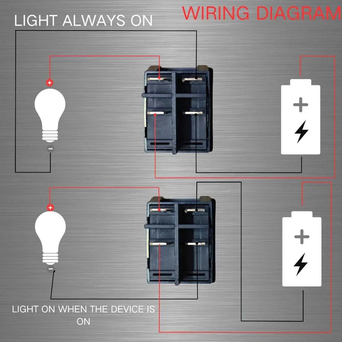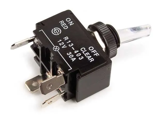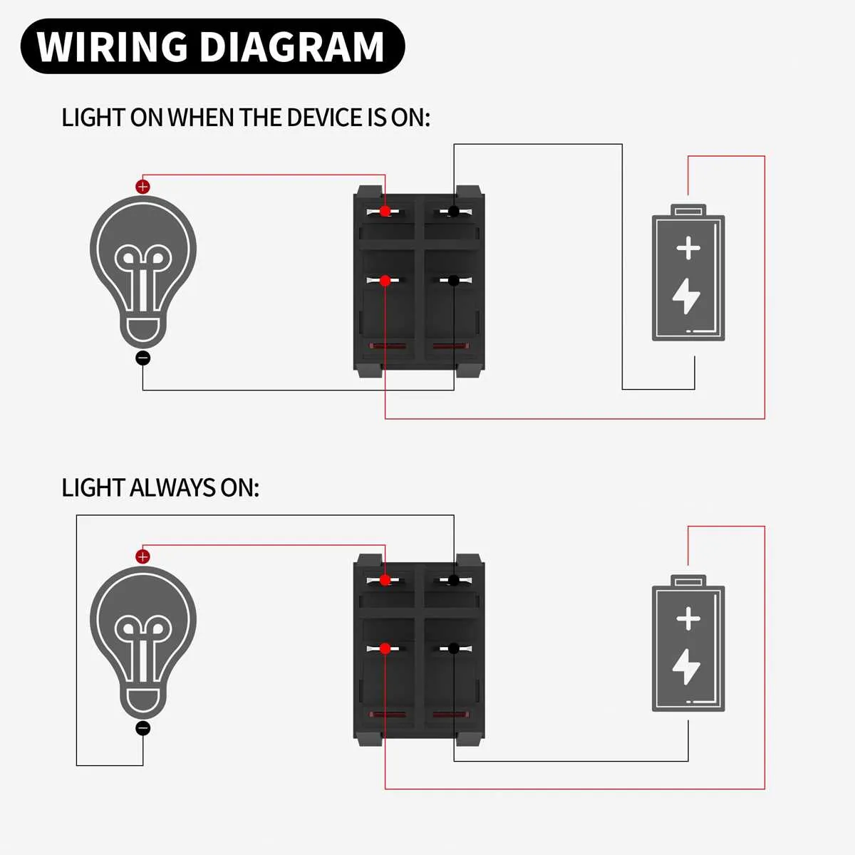
Use the two center terminals for power input: one for positive voltage, the other for ground. These are typically labeled as terminal 2 and terminal 3. Connect your power source accordingly, ensuring polarity is correct for the load type.
The outer contacts, often numbered 1 and 4, serve as outputs. Terminal 1 will connect to your device when the lever is in one position, and terminal 4 activates when it’s flipped to the opposite side. For single load applications, use only one of the output leads and leave the unused one isolated.
For illumination: If your component includes an internal light, one of the outer points may double as a contact for the lamp circuit. Check continuity with a multimeter before connecting. An internal resistor may be present; verify voltage compatibility to avoid damage.
Important: Never connect both output lines to separate loads simultaneously unless explicitly supported by the unit’s internal layout. Incorrect use can lead to short circuits or component failure.
4 Connector Rocker Control Setup Guide

Connect terminal 1 to the positive lead from the power source. Terminal 2 must go directly to the accessory or device being controlled. Terminal 3 serves as ground; link it to the vehicle or chassis ground. Terminal 4 is typically used for an optional LED indicator and should connect to the same power source as terminal 1 or a separate low-voltage feed, depending on the illumination behavior required.
Use a multimeter to verify continuity before applying voltage. Insulate all contacts using heat-shrink tubing or electrical tape to avoid accidental short circuits. For DC applications, ensure polarity is correct–reversing connections may damage components.
Identifying Terminal Functions on a 4 Pin Toggle Switch

Use a multimeter in continuity mode to determine which contacts are internally connected when the actuator is flipped. Start by labeling all four terminals: A, B, C, and D. Test pairs A–B, A–C, A–D, then repeat for B–C, B–D, and C–D. Mark the pairs that show continuity when the control is engaged.
If only one pair shows continuity at a time depending on position, it’s likely a Single Pole Double Throw (SPDT) setup. In this case, one contact acts as the input (common), and the other two serve as outputs, alternating depending on the lever’s state. The fourth terminal may be a ground or illumination lead–check if it connects to a chassis or LED.
For versions with built-in lighting, test for diode behavior using the meter’s diode mode. Connect leads across various pairs to identify the anode and cathode; this helps locate terminals responsible for powering the internal light. If the lamp only activates with the lever flipped, the light is wired in parallel with the load.
Wiring a 4 Terminal Control to Operate a 12V DC Circuit

Use a DPST (double-pole single-throw) configuration to manage a 12V DC device. Ensure the contact rating matches the current draw. Here’s the correct layout:
- Connect terminal 1 to the 12V positive supply using a fused line.
- Join terminal 2 directly to the positive input of the DC load (e.g., a fan or LED strip).
- Terminal 3 links to ground or the negative supply rail.
- Terminal 4 connects to the ground line of the load to complete the return path.
Verify that the device is rated for the expected amperage. For inductive loads (motors, relays), install a flyback diode across the load terminals to prevent voltage spikes. Use heat-shrink tubing on all exposed conductors to prevent shorts.
Test the setup with a multimeter before powering up. The actuator should make or break both lines simultaneously, ensuring clean disconnection under load.
Troubleshooting Incorrect Behavior in a 4-Terminal Control Circuit
Verify continuity between terminals using a multimeter to identify open or short circuits disrupting operation. Confirm proper connection order according to the device’s functional layout to prevent misrouting current paths.
Check for loose contacts or corrosion at connection points, which often cause intermittent failures or signal loss. Tighten or clean contacts as needed to restore reliable conduction.
Measure voltage levels on each terminal during activation phases; inconsistent or missing voltages indicate wiring faults or component malfunction. Replace defective elements immediately.
Inspect the actuator mechanism for mechanical wear or debris obstructing full engagement, which can result in erratic or incomplete switching actions.
Review the load and power source compatibility to avoid overcurrent or undervoltage conditions causing unstable circuit performance.
Utilize a schematic specific to the 4-terminal configuration to cross-check all linkages and ensure they match the intended control logic without unintended cross-connections.