Table Of Contents. Terms & Conditions. Wiring Diagram.
Installation Overview. Mounting & Wiring Instructions.
Testing Mechanical & Electrical Hookup. Valve Connector (Gray).
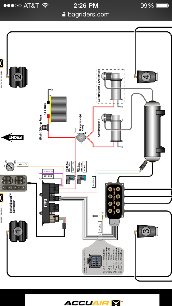
Accuair Wiring Diagram
Gray 1 – Up Solenoid 2. Gray 2 – Up Solenoid 3.

Gray 3 – Up Solenoid 4. Gray 4 – Down Solenoid 4.
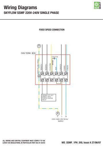
Gray 5 – Down Solenoid 3. I am wired just like this diagram. schematron.org AccuAir/schematron.org I used a vampire.
With AccuAir’s previous install record including the likes of James . we have Derek inspecting the hardware setup and running all wires into. the AccuAir e-Level™ also manages your Air Compressor(s) to keep .
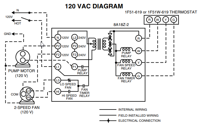
following diagram for labeling: .. Check all wiring in system including all grounds.ACCUAIR will repair or replace any failed components for the life of the vehicle given that the components were installed and operated as intended by ACCUAIR.
Upon the return of a failed component(s), ACCUAIR will determine the cause of failure. .
View and Download AccuAir AS installation, operation & application manual online. Non-Programmable Electronic Thermostat.
AS Thermostat pdf manual download. Mar 24, · Ah okay thats what your wiring showed in the first picture but your second diagram depicted the mechanical pressure switch so i thought you may have rewired it at some point. Follow me on IG @Mech_Engg.
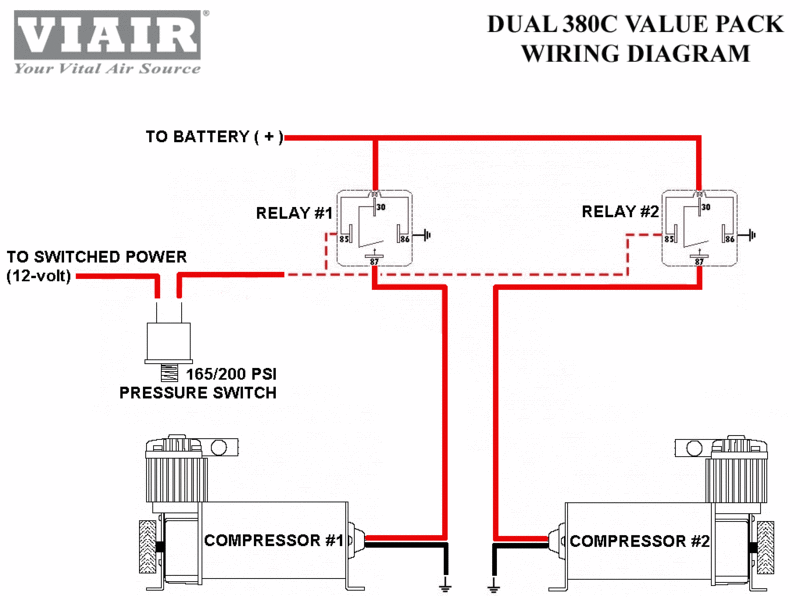
Oct 15, · Alright here is my situation, I’m attempting to wire up my accuair elevel air management, now my problem is that I’m not using the relay shown in the diagram, I know this isn’t a problem I’m just having some troubles wrapping my head around the issue at hand. Mounting & Wiring Installation System Diagram Terms & Conditions Install Overview – Page 13 – AccuAir TouchPad™ Controller Installation Manual V AccuAir Control Systems, L.L.C.
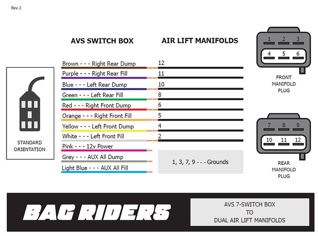
ECU Mounting: ECU Mounting Considerations • The ECU is % weather-proof and can be mounted under vehicle next to .AVS VALVE WIRING HARNESS 10 15 20 ACCUAIR VU4 TO 9 11 3 | schematron.orgRead wiring diagram (Rev 9)