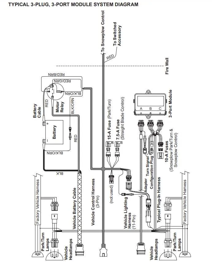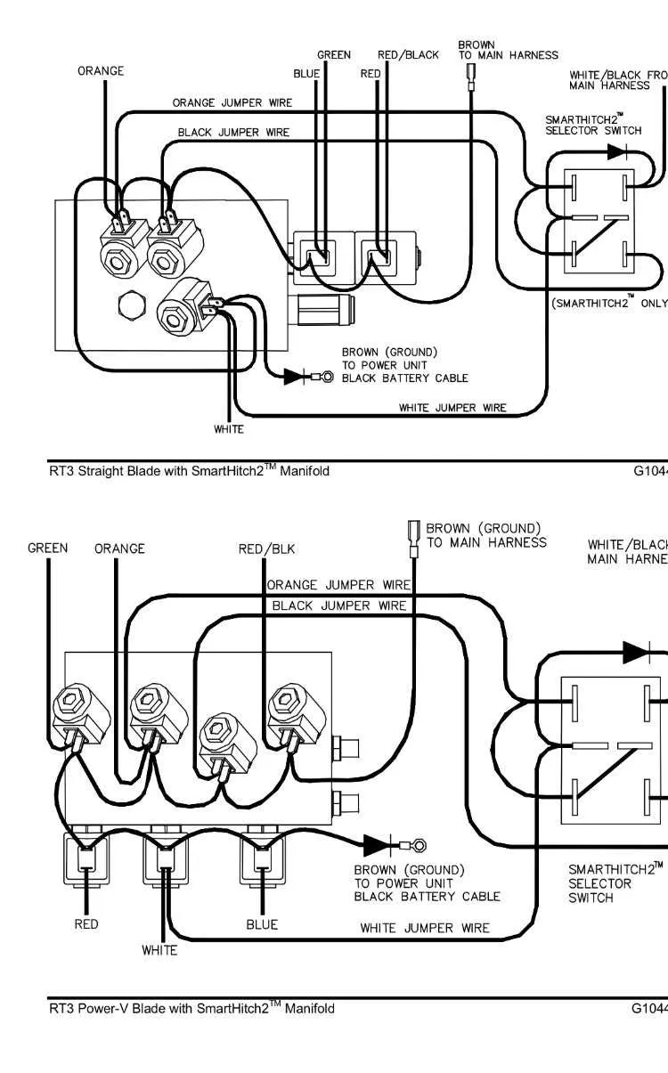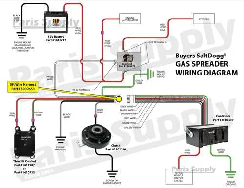
If you’re looking to troubleshoot or reconfigure the electrical system of your snow-clearing equipment, understanding the exact layout of its components is crucial. Proper connection of the control system to the activation mechanism ensures smooth operation during winter months. Follow this detailed guide to effectively connect the control circuit with the power relay, ensuring optimal performance and reliability.
Start by identifying the control terminal and the power supply inputs. These are the two main points where the system interfaces with the vehicle’s electrical network. Ensure the wiring is correctly rated for the necessary load and that all connections are secure. Use insulated terminals to prevent corrosion or short circuits that could disrupt operation in extreme weather conditions.
Verify the flow of current through the activation switch. This step is critical for proper power distribution to the drive mechanism. Check for any loose or damaged connections, particularly near the junction points. Tighten all fasteners to avoid any electrical interruptions when the system is under load.
For systems with multiple outputs, make sure that the connections are made according to the recommended sequence to avoid miscommunication between components. Always double-check polarity to prevent any damage to sensitive equipment.
Finally, ensure that the fuse and circuit protection elements are functioning properly. These safety measures are essential to protect the system from overloads. Replace any blown fuses immediately and test the system again to ensure everything is in working order.
Electrical Setup for Snow Removal System Control
For optimal performance, ensure that the main relay is connected directly to the battery’s positive terminal. The switch for activating the snow removal system should link to the activation terminals of the relay, while the secondary connection should go to the vehicle’s ground system. The signal wires from the switch must be routed to the control unit, where they will trigger the appropriate operation of the hydraulic valves.
The power supply to the main actuator should be secured with a 20-amp fuse to prevent overloading. Ensure that the power line from the battery is adequately fused and protected. A ground strap should be attached to the chassis to reduce the risk of short circuits. Additionally, verify that the ground connection on the actuator is clean and secure to ensure uninterrupted operation.
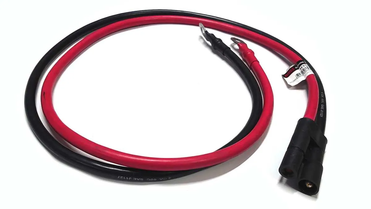
Use heavy-duty automotive-grade wires capable of handling high currents. The positive leads should be routed with a secure connection to the main terminal block, ensuring no loose ends. Avoid running the wiring close to any hot surfaces, as this can lead to insulation breakdown over time.
Double-check that the activation circuit is free of any corrosion, especially at the connectors, as this can interrupt the electrical flow and impair performance. Regularly inspect the system for any wear and tear, and ensure that all connections are free of dirt or moisture buildup to prevent system failure.
Understanding the Electrical Setup for Snow Removal Equipment

Ensure the correct power flow to your snow equipment’s electrical components by following these steps:
- Check the Control Module: The main control unit must be securely connected to the battery’s positive terminal. Ensure no loose connections that could interrupt power.
- Verify Grounding: A solid ground connection is crucial for the system’s performance. It prevents electrical issues and reduces the risk of malfunction. Attach the ground wire firmly to a clean, unpainted metal surface on the vehicle frame.
- Power Supply to Activation Coil: The activation circuit should be linked to the vehicle’s main battery. Double-check the wire’s thickness to handle the load efficiently. Use a wire gauge appropriate for your setup to avoid overheating or power loss.
- Control Switch Connections: The switch on the dashboard or handle should correspond to the correct signal wires. Ensure these are connected to the activation component, delivering the right command when the switch is engaged.
- Signal Integrity: Use high-quality connectors to maintain strong communication between components. Weak or corroded connectors can lead to unreliable responses, causing operational delays.
- Fuse Protection: Incorporate a fuse in the power feed circuit to protect against surges. Always use a fuse that matches the component’s current draw. If the fuse blows, check for short circuits or faulty components.
- Test After Installation: After assembling all parts, perform a thorough test. Check the system’s response to the control signals, ensuring smooth activation and deactivation cycles.
Follow these guidelines to ensure optimal function and longevity of your snow removal unit’s electrical setup.
Troubleshooting Electrical Connections for Snow Removal Systems

First, check the fuse box for blown fuses, especially for circuits connected to the control unit. A blown fuse can prevent the entire system from functioning, and replacing it may resolve the issue immediately.
Next, inspect the connections between the controller and the actuator system. Loose or corroded terminals can cause intermittent or complete failures in operation. Ensure all connections are tight and free from rust or dirt buildup.
If the system isn’t responding, verify that the relay is receiving power. Use a multimeter to check for 12V at the terminal where the power input connects. If the reading is lower than expected, the power source may be the issue.
Test the control switch next. If the switch isn’t engaging properly, it might be defective or have poor contact inside. You can replace the switch or clean its contacts to ensure better connectivity.
Lastly, trace the ground connection from the control unit to the vehicle’s chassis. A weak or broken ground is a common cause of failures, especially during cold weather. Ensure the ground wire is securely attached and free from corrosion.
Step-by-Step Guide to Replacing Plow Control Circuit Connections

Begin by disconnecting the vehicle’s battery to ensure no electrical current is flowing during the repair. This will prevent any short circuits or accidents while working with the control system.
Next, locate the electrical components near the lifting mechanism and identify the damaged or corroded leads. Carefully remove any dirt or debris from the area to avoid contamination when working on the connectors.
Using a wrench, unfasten the bolts securing the electrical box or housing. Once removed, take note of how the old connections are arranged. Take a clear photo or draw a quick sketch for reference to ensure accurate reassembly.
Remove the damaged cables by loosening the terminal screws and pulling the wires free. Make sure to disconnect each wire one at a time to avoid mix-ups. Keep track of color coding and terminal locations to prevent errors when reconnecting.
Cut the new cables to the appropriate lengths. Stripping the ends of each wire carefully will allow for a clean connection. Be cautious not to damage the wire strands, as this could lead to poor electrical contact.
Install the new leads by sliding the exposed wire into the terminal connectors. Tighten the screws securely to ensure a strong electrical connection. Double-check that each terminal is properly tightened and not loose.
After securing all the new cables, reassemble the electrical housing and secure it with bolts. Be sure that all connectors are reattached correctly according to the reference photo or sketch you made earlier.
Before testing the system, reconnect the vehicle’s battery. Power on the equipment and test the functionality by engaging the lifting mechanism. Observe the response and check for any irregularities in operation. If everything works smoothly, the installation is complete.