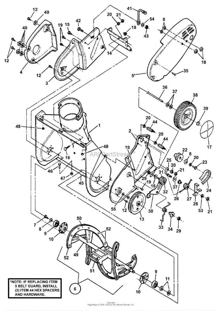
Inspect the routing pattern beginning at the clutch assembly: the flexible loop must pass cleanly around the stationary tensioner and engage directly with the transmission pulley underneath the main housing. Any deviation in angle or slack can cause slippage or premature wear.
Use a reference point near the engine shaft: the circular path wraps tightly around the primary spindle before continuing under the frame toward the rear axle mechanism. Ensure it clears the friction plate without contact to avoid heat damage.
Measure and verify alignment with factory-stamped indicators along the frame rails. These small notches are designed to help position the elastic loop correctly across both the power transfer gear and the auxiliary idler. Misalignment often results in inconsistent propulsion or sudden disengagement during use.
For older models, cross-reference component paths with model-specific schematics etched near the underside cover panel. The loop’s journey often differs depending on chassis generation, and even minor variations in guide pulley size will alter optimal tension path.
Precise Routing for Traction Assembly
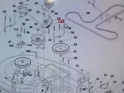
Ensure the tension mechanism aligns with the upper pulley near the rear axle. Route the reinforced loop under the engine-mounted wheel and over the transmission spindle. Confirm that the V-groove side contacts each rotating surface properly.
Correct positioning: Pass the flexible connector through the center guide between the primary and secondary gears, maintaining tension by adjusting the idler spring to 3/8-inch preload.
Common issue: Misalignment near the mower deck housing often results in reduced propulsion. Always verify the path clears the deck lift arm and mower engagement arm.
For models with hydrostatic systems, thread the reinforced band behind the cooling fan hub and under the drive sheave, avoiding contact with the thermal bypass hose. Use a flat-head tool to guide the band over the lower keeper without overstretching the material.
Locating and Identifying the Correct Drive Belt on Your Ariens Model
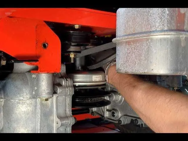
Begin by checking the model and serial number located on the frame near the left rear wheel or beneath the seat. This information is critical for selecting the precise replacement component.
- Inspect the underside of the cutting deck to locate the path of the tension system. Use a flashlight to trace the pulleys and check for worn or misaligned components.
- Refer to the part identification label, typically adhered near the engine bay or inside the hood, where routing paths are shown with pulley numbers.
- Compare the current tensioner setup with your manual’s pulley schematic. Tension springs should align properly and be free from cracks or deformation.
- Remove the cutting deck for better access to the primary pulley assembly.
- Check the upper and lower transmission pulleys for signs of wear or looseness.
- Match the length and width of the existing loop to OEM specifications using calipers or a measurement tape.
For zero-turn models, double-check that both hydrostatic transmission sheaves are turning freely before identifying the specific loop needed for optimal power transfer. Always verify compatibility using the OEM part number rather than relying on appearance alone.
Step-by-Step Guide to Accessing and Inspecting the Belt Path
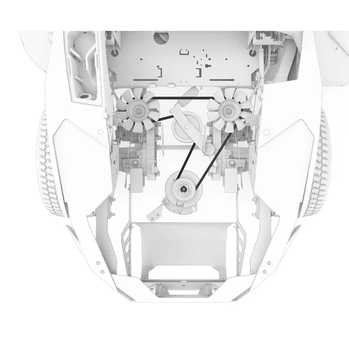
Start by disconnecting the spark plug to eliminate the risk of accidental startup. Secure the unit on a flat surface and engage the parking brake to stabilize the frame.
Remove the deck by detaching the cotter pins and releasing the height adjustment arms. Slide the deck outward to expose the internal layout beneath the chassis.
Locate the tensioning system–usually spring-loaded–and note the route of the flexible loop around pulleys and spindles. Document the configuration with a photo before proceeding.
Check for fraying, cracks, or uneven wear on the rubberized loop. Inspect each guide pulley for wobble, misalignment, or seizing, and ensure the tensioner operates smoothly without binding.
Spin the mandrel pulleys manually to detect noise or resistance. Verify all idlers are mounted firmly and rotate freely. Pay special attention to the routing near the engine pulley and rear-mounted transmission.
Reassemble the deck by reversing the disassembly steps. Confirm that all fasteners are tightened and all linkages are correctly aligned before reconnecting the spark plug.
Common Misalignments and Tension Issues in Drive Belt Installation
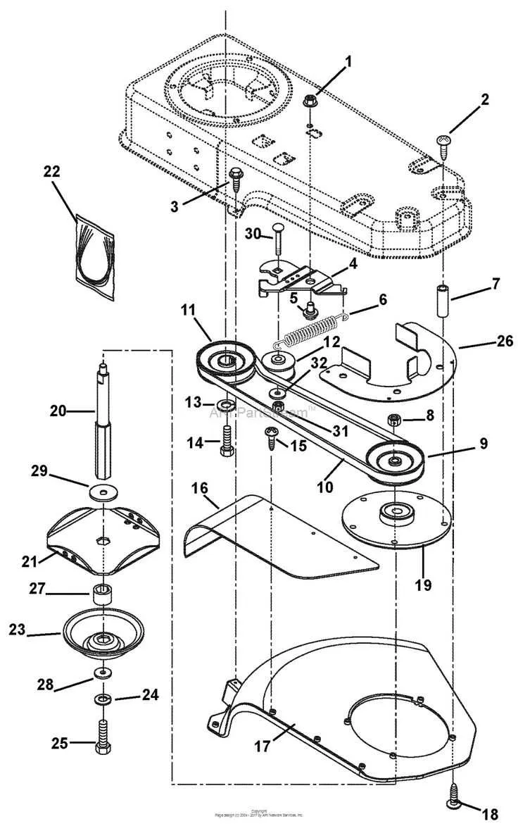
Ensure both pulleys are perfectly aligned; even a 2–3 mm deviation can cause premature wear or lead to slippage during operation. Use a straightedge tool along the faces of both sheaves to confirm parallel positioning.
Do not overtighten. Excessive tension reduces component lifespan and can bend shafts. Maintain a deflection of approximately 1/2 inch under moderate thumb pressure at the midpoint between pulleys.
Inspect idler arms for free movement. A seized or stiff tensioner prevents self-adjustment, often causing erratic function or noisy operation.
Replace any grooved or glazed contact surfaces. Worn pulley channels result in poor grip and increase thermal buildup, especially under load.
Check for sidewall fraying or polished edges. These are clear indicators of mistracking or misaligned tension components. Correct by adjusting guide brackets or repositioning spring mounts.
Ensure spring preload is correct. A weakened or overextended spring compromises consistent pressure, leading to inconsistent transfer efficiency.