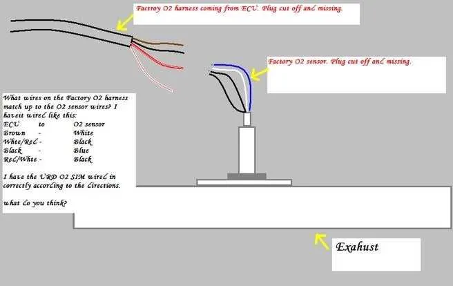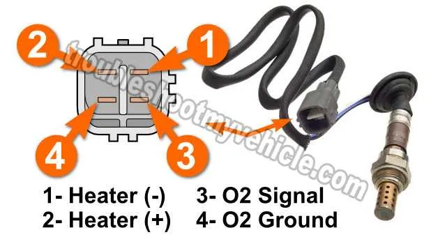
Ensure proper identification of each lead to avoid incorrect connections when installing or replacing this key engine management part. The component in question typically features four terminals, each serving a specific role in the system’s functionality. Two are responsible for heating elements, while the other two provide crucial signals for the control unit’s operation.
Begin by confirming the roles of each connection: The first pair is dedicated to the heating circuit. These terminals regulate the internal temperature, ensuring the component operates at the correct levels. The second pair is crucial for sending the measured output to the engine control unit. Typically, one carries a voltage reference, while the other transmits a signal relative to the air-fuel ratio.
Incorrect handling of these connections may lead to a malfunctioning system, reduced fuel efficiency, or even engine damage. Pay attention to the polarity of each lead, as some parts are sensitive to reverse connections. Always follow manufacturer specifications for voltage and resistance to avoid damage.
When completing the installation, ensure a stable ground connection to avoid erratic readings. Use high-quality connectors for better long-term reliability and to prevent corrosion over time. In high-performance or modified engines, consider upgrading wiring to ensure better current flow and optimal component performance.
4 Wire Oxygen Sensor Wiring Diagram
To successfully connect a four-conductor device, ensure the following pinout connections:
- Pin 1: Connect to the power supply for the heating element. This provides necessary heat for the probe’s proper operation.
- Pin 2: Attach this to the ground to complete the circuit, ensuring that the heating element functions correctly.
- Pin 3: This pin transmits the voltage signal generated by the probe to the engine control unit (ECU) for real-time air-fuel mixture analysis.
- Pin 4: Connect to the sensor return, which works in conjunction with the signal wire to help with the precise measurement of exhaust gases.
Follow these instructions carefully to maintain accurate readings and system reliability. Proper insulation and secure connections are crucial to avoid interference or malfunction. Regularly inspect for wear or corrosion that could impair functionality.
How to Identify the Wires in a 4 Wire Oxygen Sensor

Begin by locating the color codes on the connector. Each lead typically has a distinct color representing its function. For example, the black or brown lead is usually ground, while the white or grey one often transmits the signal to the engine control unit (ECU).
Signal transmission is managed by the wire linked to the sensor’s core element. This lead communicates the readings from the active element inside the unit. The voltage generated by this component is used to adjust the air-fuel mixture ratio for optimal engine performance.
The power supply lead provides the necessary voltage for the device to function, typically 12V or 5V. This connection is often red or orange in color. This is essential for keeping the internal heater active, ensuring fast response times when the engine is cold.
Lastly, the heater ground is critical for managing the temperature of the sensor’s internal element. It’s commonly connected through a separate ground lead that enables the heater to maintain the appropriate working temperature for accurate measurements.
Confirm the function of each lead with a multimeter if color coding is unclear. Testing for voltage at different points while the engine runs can help you verify the functionality of each connection.
Step-by-Step Guide to Connecting a 4-Pin Emission Monitoring Unit
Start by identifying the four essential connections needed: two for power, one for signal, and one for ground. The power pins connect to the vehicle’s ECU or PCM, ensuring the unit receives the correct voltage to function properly. Typically, one of these pins will be a 12V supply, while the other will serve as a return path for the electrical system.
Next, locate the ground terminal, often marked clearly on the unit. Attach this to the vehicle’s chassis or another suitable grounding point, ensuring a solid connection to prevent issues with performance or false readings.
The remaining pin will carry the voltage signal, which needs to be routed to the corresponding port on your vehicle’s control module. This data is used to regulate the air-fuel mixture and monitor exhaust emissions. Use a precise, secure method to make this connection to avoid any intermittent or inaccurate data transmission.
When installing, ensure the unit is positioned correctly in the exhaust system for optimal data gathering. The connection cables should be routed away from high-temperature areas or moving parts that could cause wear or short-circuiting.
Before completing the installation, double-check each connection for tightness and proper insulation to prevent any electrical faults. Once everything is in place, reconnect the vehicle’s battery and test the system for functionality. If the connection is correct, the unit will start sending real-time data to the ECU.
Troubleshooting Common Issues with 4 Wire Oxygen Sensor Connections
Ensure proper voltage supply to the component’s heater circuit. If the heater is malfunctioning, you may experience poor performance or delayed response. Check the heater circuit for continuity and replace any blown fuses or damaged components.
If the signal readings are inconsistent or the device seems unresponsive, inspect the signal and ground connections. Ensure they are securely attached and not corroded. Corrosion or loose connections often lead to incorrect readings and poor engine performance.
Examine the ground path, as a faulty or incomplete connection can cause inaccurate feedback. Make sure the grounding terminal is clean and tightly fastened. Inconsistent ground contact is a frequent cause of malfunctioning feedback loops.
If the component is showing error codes related to incorrect air-fuel mixture, check the voltage of the reference line. The reference signal should remain steady; fluctuations may indicate damage to the wiring or electrical components connected to the device.
In some cases, a poor connection at the connector points can cause intermittent failure. Verify the connector is properly seated and free from dirt or moisture. Moisture can cause short-circuiting and disrupt normal operation.
Lastly, a faulty unit may be the culprit. If all connections are sound and proper voltage is present but issues persist, consider replacing the component itself. Over time, these devices degrade and may need replacement to restore optimal functionality.