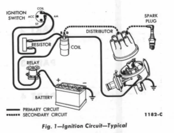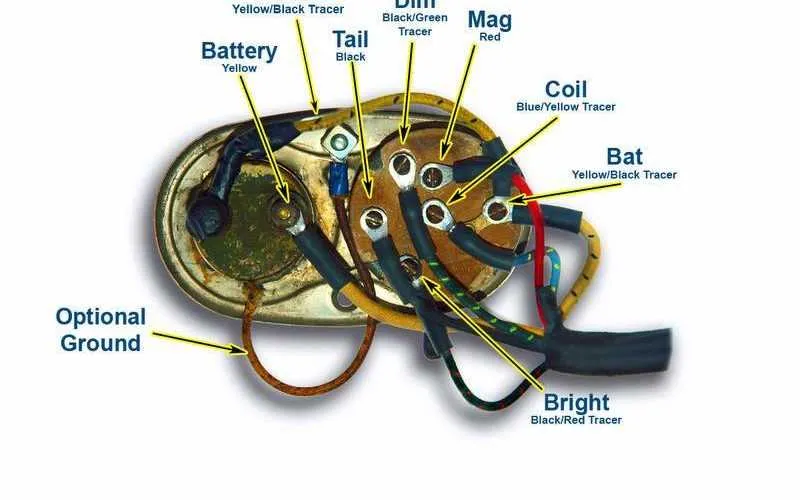
To ensure optimal performance of the engine’s electrical pulse distributor, it is crucial to correctly link the ignition pack terminals to the control unit and power source. The primary terminal should connect to the 12-volt supply via a fused line, while the secondary output must feed the distributor cap and spark plugs with proper timing.
Pin assignment accuracy directly affects combustion efficiency and prevents misfires. Verify the signal wire routing from the engine control module to the coil pack, confirming each lead matches its designated socket according to the factory specification.
Incorrect terminal connections can cause voltage drops or coil overheating, leading to ignition failure or component damage. Use a multimeter to test continuity and resistance values before finalizing the assembly, ensuring compliance with technical manuals for your specific engine model.
Engine Spark Module Connection Layout
Locate the high-voltage terminal that links directly to the distributor cap. The primary power input should come from the vehicle’s battery via a fuse-protected ignition switch circuit. Identify the control wire leading to the ignition control module or engine computer, usually marked with a distinct color such as pink or orange.
Connect the ground terminal securely to the engine block or chassis to ensure proper current flow and prevent misfires. The secondary output must route to the spark plug wires through a distributor or coil pack, depending on the specific engine setup.
Use a digital multimeter to verify continuity between the power source and the module’s input terminal before final assembly. Ensure all connectors are free of corrosion and fit tightly to avoid voltage drops.
For systems with multiple modules, follow the numbered or color-coded leads to match the firing order. Incorrect link placement can lead to engine stalling or poor performance.
Identifying Wire Colors and Connector Types on Ford Ignition Coils
To correctly recognize cable colors and connector styles on these automotive components, focus on these standard signals and plug configurations:
- Primary Circuit Wires:
- Typically, the positive lead is red or red with a stripe.
- Ground or negative connections often appear black or brown.
- Control wires linked to the ignition module may use colors like green or yellow.
- Secondary Circuit Connections:
- High-tension output is connected through a single terminal or integrated plug, usually without color coding, but clearly marked on the part itself.
- Common Connector Types:
- Two-pin plastic connectors with locking tabs for the primary circuit.
- Single spade terminals or blade connectors are often found on older models.
- Some versions use sealed connectors to prevent moisture intrusion, identifiable by rubber gaskets.
Check the component’s part number or service manual for exact color codes and plug types, as variations occur between model years and engine configurations.
Step-by-Step Guide to Connecting the Spark Coil in Ford Models
Begin by locating the main power lead on the distributor module. Connect the positive terminal of the spark device to the 12V source, ensuring a secure and clean connection to avoid voltage drops. Attach the negative terminal to the control unit, usually marked as the trigger input.
Identify the secondary output port and link it to the high-tension cable leading to the spark plugs. Confirm that the connection is tight to prevent misfires caused by loose contacts. Use dielectric grease on terminals to protect against corrosion.
Verify that the ground wire is firmly attached to the chassis or engine block; a poor ground will disrupt current flow and cause starting issues. Double-check all connectors for correct polarity and secure fitment before powering the system.
After completing connections, perform a continuity test on each lead with a multimeter to ensure circuit integrity. Finally, start the engine and monitor for consistent spark delivery, listening for any irregular sounds that might indicate a faulty setup.
Troubleshooting Common Electrical Issues in Vehicle Spark Module Circuits

Start by checking the continuity of the primary and secondary cables using a multimeter. A broken or high-resistance line often causes weak or no spark delivery. Inspect connectors for corrosion, especially at the plug terminals and grounding points, which may lead to intermittent faults or complete failure.
Verify the voltage supply at the power input terminal under ignition-on conditions. A drop below 12 volts indicates a problem with the main feed or fuse box. Examine the control unit signal wire for proper pulse output using an oscilloscope; an absence of pulses points to ECU or sensor issues rather than cabling faults.
| Symptom | Likely Cause | Recommended Action |
|---|---|---|
| No spark at the plug | Open circuit in power lead | Test continuity; repair or replace damaged cable |
| Weak or inconsistent spark | Corroded connectors or poor ground | Clean terminals; ensure secure grounding |
| Intermittent misfire | Loose connector or broken internal wire | Reseat connections; replace faulty component |
| No voltage at supply pin | Blown fuse or faulty relay | Inspect and replace fuse/relay as needed |
Do not overlook harness damage caused by engine heat or vibration, which often manifests as cracked insulation and short circuits. Use dielectric grease on terminals to prevent moisture ingress and prolong contact reliability. Regular inspection and prompt repair of defects in these circuits help maintain stable spark generation and avoid drivability issues.