For optimal performance of your snow clearing machine, it is essential to regularly check the mechanical components. Understanding the layout of each section and the connections between them is critical to identifying potential wear or damage.
Start with the hydraulic system. Ensure all hoses are tightly connected, and check for any leaks or signs of wear. The hydraulic pump must be properly lubricated to avoid overheating and ensure smooth operation during heavy use.
Next, focus on the lifting mechanism. Verify that the linkage is free from rust or debris. Regularly inspect the pins and bolts, tightening them as needed to prevent movement or loosening during operation.
Finally, don’t overlook the wear edges. Replace or sharpen them as soon as they show signs of erosion to maintain efficient clearing. A clean and well-maintained cutting edge reduces strain on the rest of the machinery and improves performance during severe weather conditions.
Essential Components Overview

When servicing or upgrading your snow removal equipment, it’s crucial to understand the key components that ensure efficient operation. Begin by familiarizing yourself with the lifting mechanism, which is responsible for raising and lowering the clearing blade. This system includes a series of hydraulic cylinders that should be checked regularly for wear and leaks.
The blade mount is another critical part. Ensure that the connections are secure and free from rust, as any failure in this area can lead to equipment malfunction. Be sure to inspect the pivot pins, which are integral to the mobility of the blade. They should be lubricated to avoid friction and wear.
Lastly, don’t neglect the control system. Check the wiring connections and make sure the control panel responds accurately to input. If you encounter issues with responsiveness, it’s often related to a faulty connection or a malfunctioning switch. Regular inspection of all these components will extend the lifespan of your equipment.
Identifying Key Components in the Layout

To effectively recognize and understand the major components in the layout, focus on the primary sections and their corresponding labels. Pay special attention to the items most commonly used for assembly and maintenance.
- Hydraulic System: This is crucial for the movement of the equipment. Look for labeled cylinders and pumps, as these are directly responsible for operation.
- Mounting Brackets: These support the attachment of various elements. Ensure you identify the mounting points clearly, as these hold the entire structure together.
- Control Mechanisms: The levers and actuators that govern movement should be highlighted. Their placement is essential for both manual and automated functions.
- Frame and Structural Support: The skeletal structure serves as the foundation. Verify connections between beams, crossbars, and reinforcements to ensure stability.
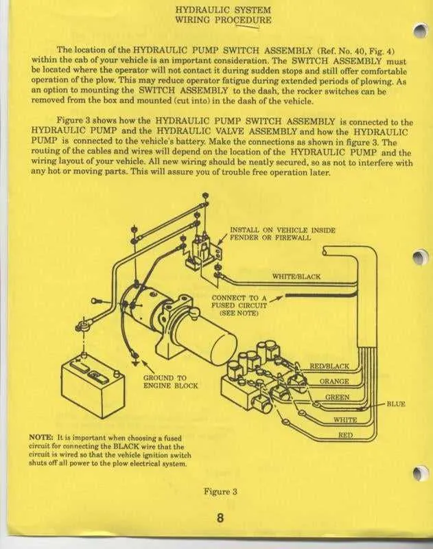
- Electrical Wiring: Locate the wiring harnesses that connect the power system to the controls. Proper identification will assist in troubleshooting and repairs.
Ensure all components are clearly marked to facilitate identification during repairs or upgrades. The more familiar you are with the layout, the more efficiently you’ll be able to locate parts during maintenance tasks.
How to Troubleshoot Common Issues Using the Diagram
Begin with the control harness: Check for continuity between connectors using a multimeter. Refer to the schematic to locate terminal positions and wire colors. Inspect for corrosion, loose pins, or pinched sections, especially near pivot points.
Next, verify hydraulic function: Use the layout to identify solenoid positions and flow paths. If angling fails, test coil resistance (typical range: 5–7 ohms) and confirm magnetism when energized. If lift is slow or unresponsive, check fluid level and filter screen for debris.
Inspect fuse block and relays: Use the wiring chart to trace circuits linked to lighting and motor relay activation. Replace any blown fuse with the correct amp rating. Swap relays with known-good units if clicking is absent on command.
Focus on actuator response: Consult the schematic to determine proper power feed and ground points. Use jumper wires to test direct function. If cylinders stall mid-operation, inspect for internal bypass or damaged seals indicated in the exploded layout.
Test controller interface: Refer to the control connector pinout to validate signal output. If buttons are unresponsive, measure voltage at output pins while pressing each control. Replace interface unit only after confirming all wiring paths are intact.
Step-by-Step Guide to Replacing Components Using the Visual Layout
Start by disconnecting the power supply to the unit to prevent accidental activation during maintenance. Ensure the control switch is in the off position and the vehicle is turned off.
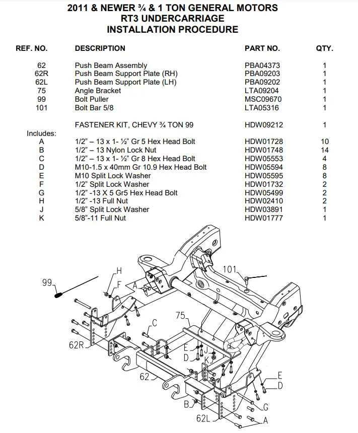
Identify the faulty element by referencing the illustrated layout. Focus on item numbers and their corresponding labels to avoid confusion. Each item is assigned a unique code; verify it against the reference list before proceeding.
Use the correct tools based on fastener types shown in the schematic. For example, if a spindle support is secured with hex bolts, use a socket wrench of matching size. Avoid using adjustable tools to maintain torque accuracy.
Disassemble in reverse order of the installation sequence shown in the blueprint. Remove brackets, retainers, and seals carefully. Keep small hardware organized in labeled containers for easy reassembly.
Install the new segment by following the visual guide in forward order. Tighten all bolts to manufacturer-specified torque values. If a locking pin or spacer is involved, ensure it is seated flush with adjacent hardware as illustrated.
Reconnect hydraulic lines or wiring only after verifying the new module is fully secured. Double-check hose orientation and connector alignment with the layout before restoring power.
Test the system by activating controls and observing movement or response. If alignment or function appears off, consult the visual aid again to confirm each piece is correctly placed.