
Diagram showing service entrance, conduit/wire size, main disconnect size, grounding electrode/conductor size, feeder . Seismic design category: B or C – See Figure R (2).
Weathering .. Absorption trench, Bed or Pit.
BWD ® is your go-to source for a full line of accessory and electronic relay solutions that support all key engine components and systems, including: Air. Items 1 – 8 Staples are 16 gage wire and have a minimum 7/inch on diameter crown width.
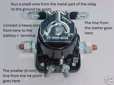
c. . pressures acting toward and away from building surfaces per Section R Number of braced wall lines (per plan direction)c, Any story, 2, Deep furrowing of bed joints that produces voids shall not be permitted. Results 1 – 48 of 58 Multi-use Relay BWD R For Variou GM Cars Trucks BWD R Door Lock Relay – WIRING RELAY (Fits: More than one vehicle) ..
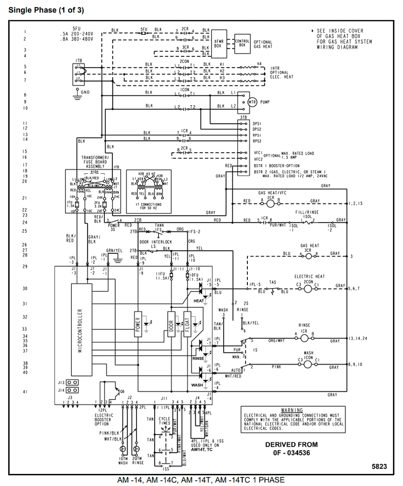
the compatibility chart to verify the position of this part on your vehicle. Wiring Diagram for the Alpha Sun 24XL V tanning bed.
There are two images for the Alpha Sun 24XL V version, both of which are needed.4 Wiring Pigtail Kits 4. • When you are looking at a wiring diagram on a or newer vehicle, click on a connector number (C Number). It will take you to the Connector Face View page where there is a box that says “Check Wire Terminal Repair Kit that will service that terminal.
New Wire Terminal Kit. BWD is a global manufacturer of original equipment ignition products, complete quality control is maintained through the manufacturing process from componentry to finished product MSDS Sheets – No MSDS sheet available.
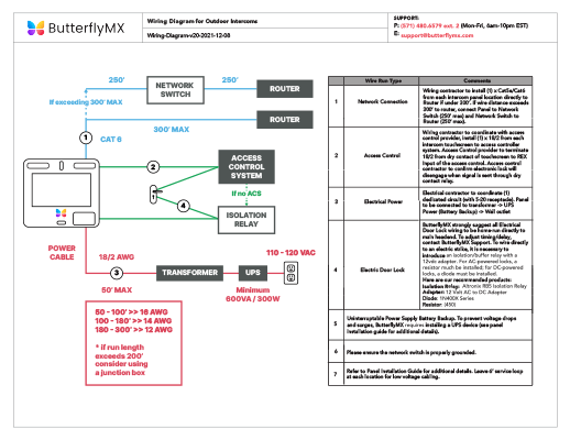
wiring to this point must be in accordance with National and Local codes. Refer to specifications on page 2 for proper wire size.
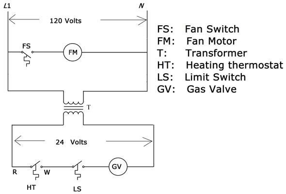
NOTE: If the wiring is to run through the wall, cut a hole in the area of the top of the back box. Run the supply wire through this hole.
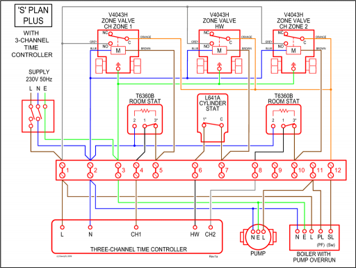
Then remove the “knockout” from the top of the box and proceed to step C. b.

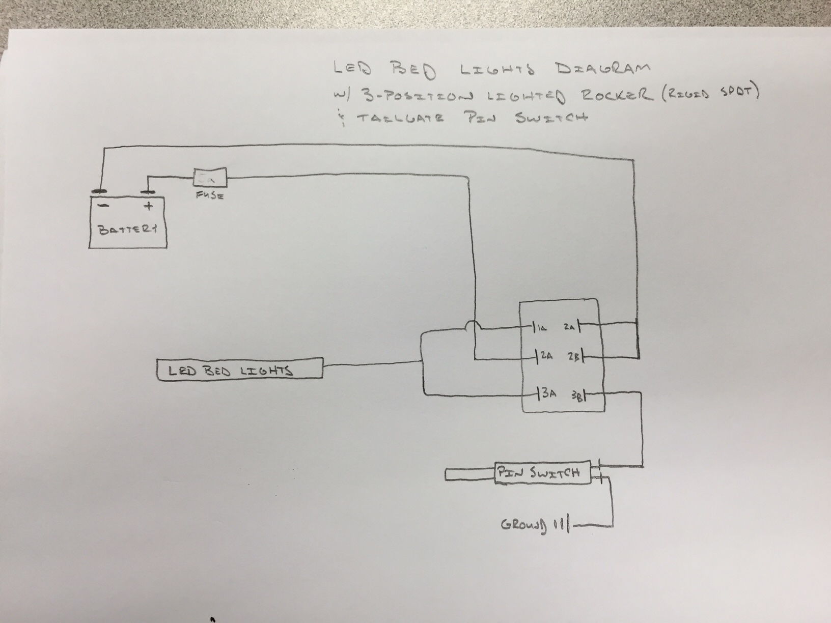
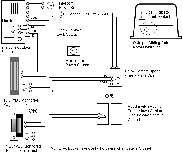
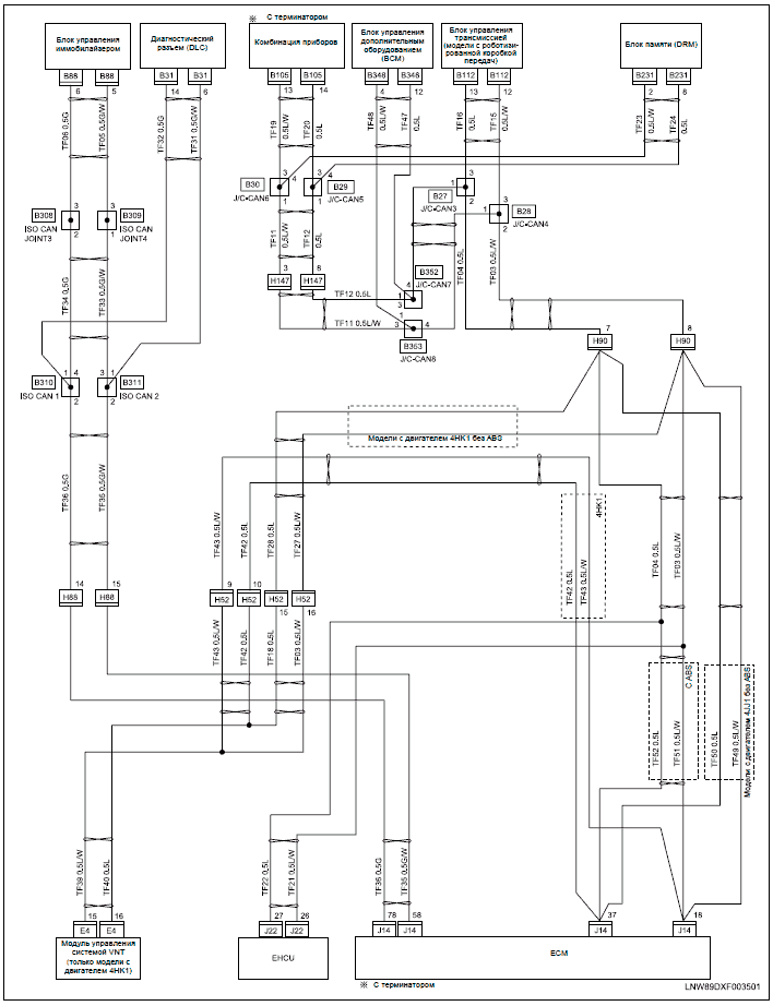
Wiring Wiring Diagram. We have located a lot of references concerning Pt Bwd Code Wiring Diagram but we believe this one is the greatest. I hope you would also acknowledge our opinion.
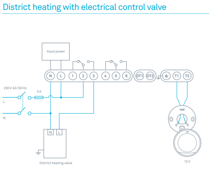
This picture has been uploaded by our team and is in category tags section. Aug 19, · Bwd Voltage Regulator Wiring Diagram – A PCB Layout is the resulting design from taking a schematic with specific components and determining how they will physically be laid out upon a printed circuit board. To produce a PCB Layout, you must know the associates of components, component sizes (footprints), and a myriad of.Electrical | BWDCARQUEST – Part Information
