Locate the primary power distribution unit under the dashboard or in the engine compartment to quickly identify and troubleshoot electrical components. Understanding the precise arrangement of protective elements prevents unnecessary replacements and saves time during repairs.
Each circuit protector is designated for specific systems such as lighting, ignition, or air conditioning. Refer to the detailed layout to ensure correct identification and maintain system integrity when inspecting or replacing components.
Use the schematic to verify the amperage ratings assigned to each protective element to avoid overloading circuits and potential damage. Proper knowledge of the layout also aids in diagnosing intermittent electrical faults and optimizing vehicle safety.
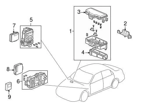
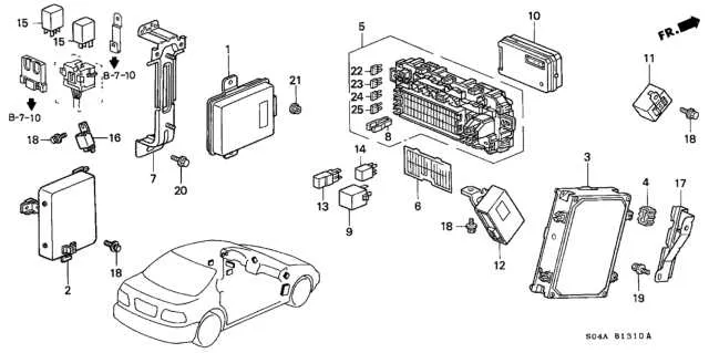
Wiring Layout for Vehicle Electrical Panel of the Year 2000 Sedan
Refer to the following detailed schematic to identify and troubleshoot the panel responsible for circuit protection in the mid-size sedan model released at the turn of the millennium. Proper identification of each element ensures efficient maintenance and safe replacement.
- Main Power Relay: Controls distribution to critical systems including ignition and fuel injection.
- Headlight Circuit Protector: Rated at 15A, this element safeguards front illumination components.
- Cooling Fan Protector: A 30A link dedicated to radiator and condenser fan motors.
- Radio and Accessories Link: Usually 10A, securing audio systems and auxiliary outlets.
- Interior Lighting Protection: Often 7.5A, guarding cabin illumination and dashboard lights.
- Horn Circuit Link: 10A capacity designed for the vehicle’s signaling device.
- ABS and Brake System Link: 20A safety element for anti-lock braking and related electronics.
When replacing any component within this assembly:
- Always disconnect the battery to prevent electrical shock or shorts.
- Use amperage-matched substitutes to avoid circuit damage.
- Consult the vehicle’s maintenance manual for exact location of each protective element.
- Inspect for corrosion or loose connections within the casing before installation.
Accurate referencing of this layout ensures optimized functionality and safety for electrical circuits in the vehicle model from this production year.
Locating and Identifying Electrical Panel Compartments in the Vehicle

The primary electrical panel is positioned beneath the dashboard on the driver’s side, near the steering column. It is accessed by removing a small plastic cover that reveals the cartridge holders controlling various circuits. A secondary panel is situated in the engine compartment, adjacent to the battery, enclosed in a black plastic casing marked with symbols indicating its purpose.
To correctly identify each cartridge holder within these compartments, refer to the molded labels on the inside of the access covers. These labels specify amperage ratings and associated systems such as lighting, ignition, or air conditioning. Utilizing the vehicle’s service manual can provide a detailed list correlating each fuse location with its function, ensuring precise troubleshooting.
Step-by-Step Guide to Reading the Vehicle’s Electrical Protection Layout

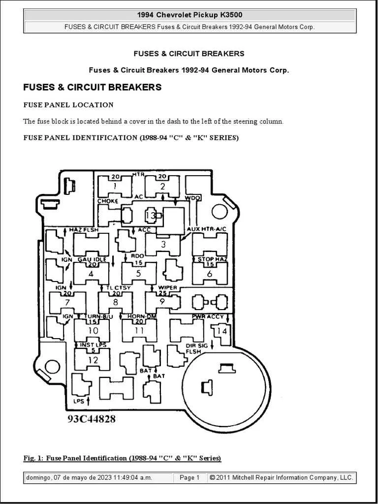
Identify the legend first. Locate the key on the schematic that assigns each numbered slot to its respective circuit function. This will clarify which electrical components correspond to each protective element.
Check amperage ratings. Each protection device has a specified current limit marked next to its position. Confirm that these values match the requirements of the associated system to prevent under- or over-protection.
Match the location to your engine bay panel. Compare the layout map with the physical compartment to ensure you are referencing the correct fuse holder. Orientation and numbering sequence may vary slightly.
Trace the circuits carefully. Follow the lines connecting each protective element to the systems they secure–such as lighting, ignition, or accessories–to understand which part is safeguarded.
Use a tester to verify functionality. Before replacing or removing any component, test for continuity or voltage to pinpoint faulty elements without guessing.
Document any changes. After servicing, mark any adjustments or replacements to maintain accurate records for future troubleshooting.
By systematically analyzing the schematic and cross-referencing with the actual electrical panel, you ensure precise identification and effective maintenance of the vehicle’s protective electrical components.
Replacing and Troubleshooting Common Electrical Component Issues in the 2000 Sedan

Start by disconnecting the negative terminal of the battery to avoid shorts during component replacement. Identify the faulty protective element by visually inspecting for melted metal strips or using a multimeter set to continuity mode. If the element is blown, replace it with an identical amperage rating to prevent electrical system damage.
When encountering repeated failures, verify the connected circuit for possible shorts or overloaded accessories. Check wiring harnesses behind the protective panel for exposed or frayed wires. Clean corrosion on contact points with electrical cleaner to ensure proper conductivity.
To remove the protective component, use needle-nose pliers or a fuse puller tool designed for this model. Avoid using higher rated replacements as this risks overheating and fire hazards. After installation, restore battery connection and test affected systems such as lighting, power windows, or audio equipment.
Regularly inspect the panel for signs of moisture intrusion or dirt buildup, which can cause erratic behavior. If problems persist despite replacements, consult the vehicle’s service manual for circuit-specific troubleshooting steps or consider professional diagnostics with specialized equipment.