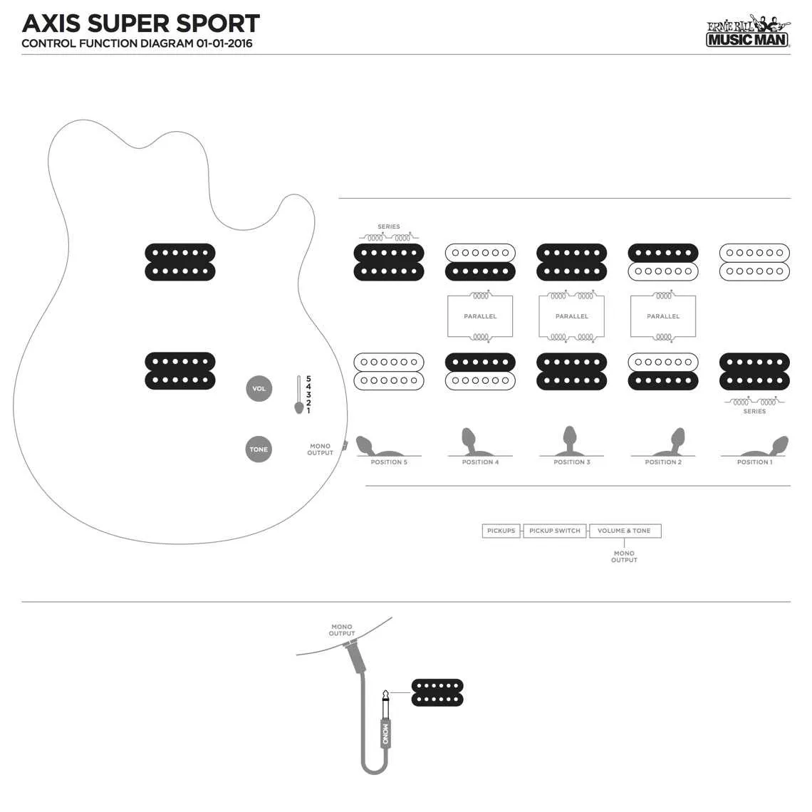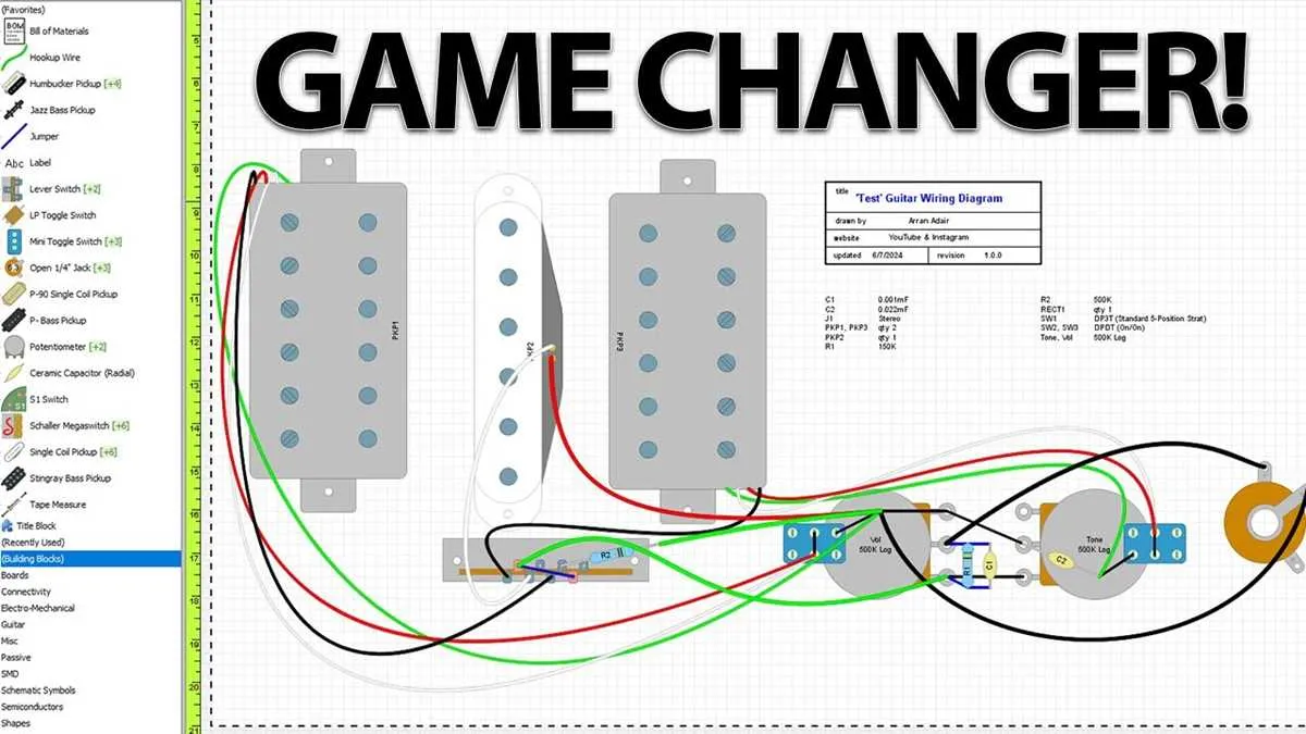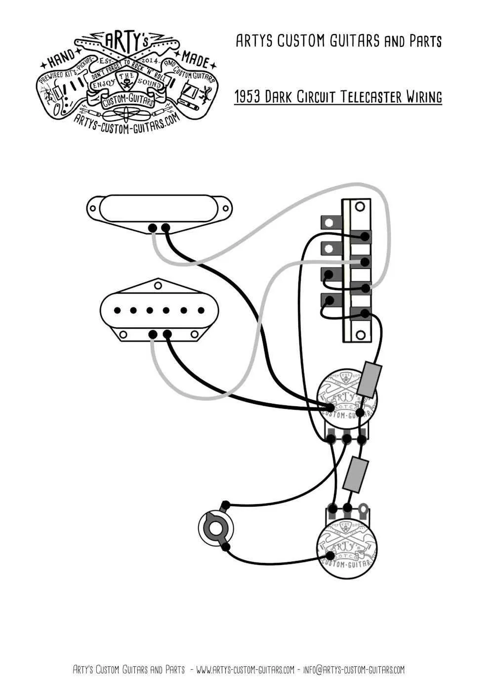
Start by selecting the right schematic tailored to your pickup configuration and desired tonal options. A well-planned circuit can significantly reduce noise and improve signal clarity, especially when integrating coil-splitting or phase-switching features.
Prioritize quality components such as reliable potentiometers and capacitors to maintain consistent performance and durability. Using standard values like 250k or 500k pots depending on your pickup type ensures optimal brightness or warmth in sound.
Focus on minimizing signal path length and solder joints to prevent unwanted interference. Employing a layout that keeps grounds consolidated can dramatically lower hum and buzz, improving overall output stability.
How to wire coil splits and phase switches for versatile tone options

Use a push-pull potentiometer or a mini-toggle switch to activate coil splitting by grounding the start or finish of the humbucker’s second coil. Connect the coil tap wire directly to the switch lug that grounds it when engaged, effectively turning the humbucker into a single-coil pickup and reducing noise while retaining brightness.
For phase switching, install a DPDT (double-pole double-throw) switch between two pickups’ hot leads. Cross-wire one pickup’s positive and negative leads to reverse its polarity. This creates an out-of-phase sound with a thinner, more nasal character, ideal for funk and rhythm styles.
Ensure all grounds are properly connected to avoid hum and signal loss. Use shielded wires for switch connections and keep lead lengths short to preserve clarity and reduce interference.
When combining coil splits with phase switching, isolate the switches to prevent signal conflicts. Map the circuit on paper beforehand to verify continuity and avoid miswiring, which can cause dead spots or unintended noise.
Test the system thoroughly after soldering each connection, verifying that each mode (full humbucker, split coil, in-phase, out-of-phase) produces clear and expected tonal changes without volume drops or buzz.
Step-by-step guide to installing and wiring push-pull pots in electric instruments
Start by selecting a push-pull potentiometer that matches the required resistance (commonly 250k or 500k) for your pickups. Ensure it fits the control cavity without obstruction.
Remove the existing knob and potentiometer from the control panel carefully. Desolder all connected wires and take note of their original positions.
Mount the push-pull pot into the cavity through the designated hole, securing it with the provided nut and washer. Tighten firmly but avoid over-torquing to prevent damage.
Identify the six lugs on the push-pull switch: typically, two rows of three terminals. One row controls the switch’s ON/OFF function, while the other row controls the pull/push mechanism.
Connect the hot lead from the pickup to the input lug of the potentiometer as per your modification plan. Use high-quality shielded wire for better signal integrity.
Solder jumper wires between the switch lugs according to the specific tone or coil-splitting function desired. Refer to manufacturer’s wiring charts for precise terminal connections.
Ground all necessary components by soldering wires to the pot casing or a common ground point. This reduces unwanted hum and interference.
Double-check all solder joints for solid, clean connections. Cold or weak soldering can cause intermittent signal loss.
Test the assembly before reassembling by plugging the instrument into an amplifier and operating the push-pull mechanism to confirm correct functionality.
Once verified, reattach knobs and secure the control plate. Perform a final operational check to ensure smooth switching and consistent tonal response.
Choosing and wiring the right capacitors and resistors to shape your instrument’s sound

Use a 0.022µF film capacitor for a balanced tone with clear highs and smooth mids in passive pickups; switch to 0.047µF for warmer, bass-heavy output. For treble bleed circuits, pair a 150kΩ resistor with a 0.001µF capacitor to maintain clarity at lower volumes.
When selecting resistors, opt for 500kΩ pots combined with a 0.022µF capacitor to retain brightness on single-coil setups. Lower the pot value to 250kΩ to darken the tone, ideal for humbucking systems.
To implement a mid-scoop, integrate a 33kΩ resistor in series with a 0.01µF capacitor across the tone control. This combination reduces mids while preserving lows and highs.
For enhanced output smoothness, wire a 1MΩ resistor in parallel with the volume control. This prevents signal loss and retains high-frequency response.
Use metal film resistors for their low noise and stability; avoid carbon composition types in critical tone paths to minimize hiss and maintain consistency.
Properly solder components with short leads to reduce parasitic capacitance. Keep capacitor leads as short as possible, ideally under 10mm, to avoid unwanted signal filtering.