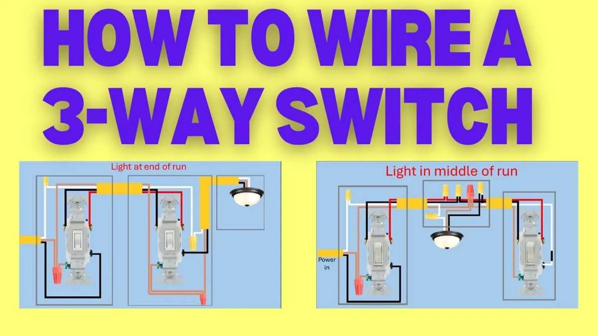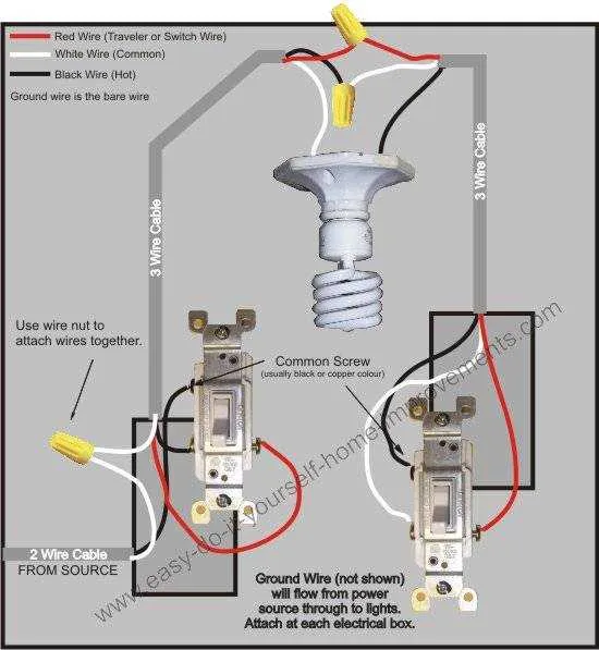
To successfully set up a lighting system that can be controlled from two or more points, you need to ensure proper connections between the terminals and the power sources. This configuration requires careful attention to the types of cables used and their placement in the control units. The key to making this system work is understanding the connections between the common terminal, traveler terminals, and how to wire them to ensure smooth functionality.
Start with the common terminal, which will serve as the entry point for power. This is where the live wire should be connected, and it will direct the current to the respective control units based on the toggle action. Next, connect the traveler wires from one control unit to the next, ensuring they are properly connected to the corresponding traveler terminals. These are the essential components that allow for remote control of the light fixture from multiple locations.
The final step involves making sure the grounding wire is securely attached to each control unit and any metal boxes, if applicable. This ensures safety in case of any electrical faults. Double-check all connections before turning the system on to avoid issues with the circuit’s operation.
Proper Circuit Setup for Multi-Location Control
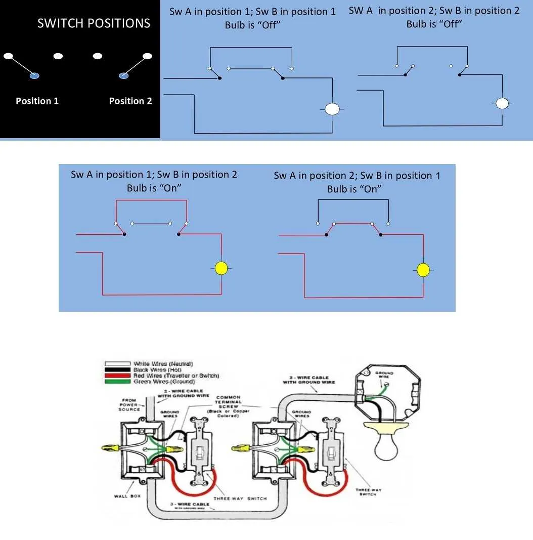
For controlling a single light from two separate points, use two-position devices that interconnect with the light fixture. The installation requires two controlling units, each with a common terminal, along with a traveler line linking them. Ensure that the power source is connected to the common terminal of one device, while the fixture is linked to the other common terminal.
The traveler cables should connect both devices’ traveler terminals, which allow for alternating the circuit path. When setting up, ensure that both terminals of each device are correctly wired to prevent malfunctioning. Additionally, verify the fixture connections to the common terminal of the second device to complete the loop.
To simplify, ensure each controlling unit’s orientation is maintained, so the current flows seamlessly in either direction depending on which device is activated. Double-check the polarity and continuity before finalizing the installation for safety and proper operation.
Understanding the Role of Common Terminal in Multi-way Circuits

The common terminal plays a crucial part in controlling the flow of electricity in multi-way circuits. It is the central point where power is either supplied to or received from the load. Properly identifying and connecting this terminal ensures that the entire circuit operates efficiently and safely.
- The common terminal is typically the darker screw or the terminal marked with a “C” on most electrical devices.
- It connects directly to the power source in a standard configuration, distributing electricity as needed.
- When wiring, the common terminal should only be connected to the hot or live wire, never to the neutral or ground wire.
Incorrect connection of the common terminal can result in malfunctioning, overheating, or even fire hazards, making its role one of the most important in these configurations.
- When using a multi-way circuit, ensure that the common terminal on one device is connected to the incoming power supply, while the other terminals handle the path for the return or alternate routes.
- On a second device in the series, the common terminal is typically where the wire carrying the returning current will be connected.
Understanding the function of the common terminal is essential for maintaining control over circuit operation and preventing electrical faults.
Step-by-Step Process for Connecting Dual Control Light Fixtures

Start by turning off the power at the circuit breaker. Ensure the circuit is de-energized before proceeding. Install two devices in the locations where you want to control the light. One will serve as the initial control, the other as the secondary control point.
Connect the common terminal of the first device to the power source, usually identified by a black or hot wire. On the second device, connect the common terminal to the light fixture, ensuring the connection is tight and secure.
Link the traveler terminals of both controls using the same color-coded wires, typically red or black. These wires will carry the current between the two control points. Ensure the connections are made to the corresponding terminals at each device.
Ground each device properly by attaching the ground wire to the green screw on both controls. Double-check all connections before closing the devices in their electrical boxes.
Finally, test the setup by turning the power back on. Toggle both devices to verify the light turns on and off from either location. If it does not work, double-check the connections for accuracy, ensuring the power source, light fixture, and travelers are correctly wired.
Common Mistakes to Avoid in Multi-Switch Setup

Ensure that the traveler wires are connected to the correct terminals. Connecting them incorrectly can cause malfunction or failure to control the light from both locations.
Double-check the positioning of the neutral wire. It should never be attached to the traveler terminals; it must go directly to the light fixture or junction box. A misconnected neutral can lead to a short circuit or failure of the system.
When installing a dimmer switch as part of the setup, ensure that it is rated for multi-location control. Using a dimmer designed only for single-location use can result in improper functionality.
Avoid improper grounding. Ground wires should be securely attached to the metal boxes and properly connected to the switches. Missing or loose ground connections can be hazardous and lead to electrical shock risks.
Confirm that the correct switch is installed in each location. Using a standard single-pole switch in place of a multi-pole unit can result in malfunction, where the light can only be controlled from one location.
Check for any loose connections before finalizing the installation. Loose terminals can cause intermittent operation, or the system may not work at all, leading to frustration and potential damage to components.