25 pin D-SUB male photo and diagram Calcomp Drawingboard 3 DB25 F w 12V to 8 pin DIN mini pinout and wiring · Centronics to LapLink adapter pinout.
Aviom analog input and output modules with DB25 multi-pin connectors are wired to jacks found on Aviom products are numbered according to the diagram. Wiring Diagrams. XLR Connectors.
1/4” TRS & TS. Connectors.
DB25 Connectors. All DB25 connectors are wired with Tascam pinout & numbering, housing.
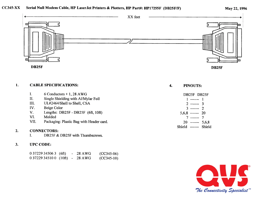
25 pin D-SUB male photo and diagram Calcomp Drawingboard 3 DB25 F w 12V to 8 pin DIN mini pinout and wiring · Centronics to LapLink adapter pinout. B&B Electronics has many reference tools for your convenience. View or download the RS pinout and COM Port Summary Card with DB25 and DB9 Pinout.Db25 Wiring Diagram ~ here you are at our site, this is images about db25 wiring diagram posted by Benson Fannie in Db25 category on Nov 22, You can also find other images like wiring diagram, parts diagram, replacement parts, electrical diagram, repair manuals, engine diagram, engine scheme, wiring harness, fuse box, vacuum diagram, timing belt, timing chain, brakes diagram.
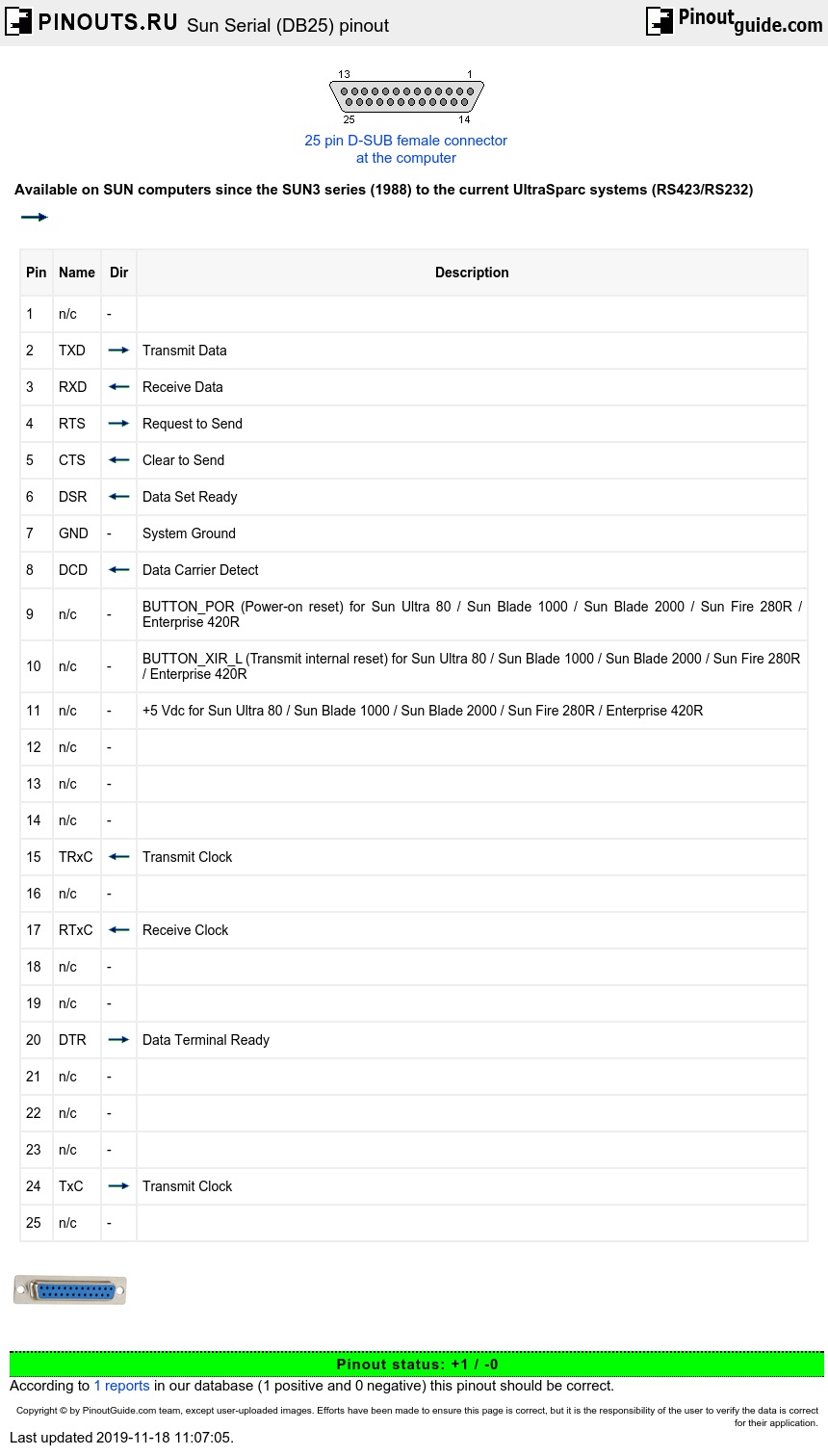
RS Cables, Wiring and Pinouts Brief tutorial and pinouts for RS, T1/E1 and V Contents DTE (PC) and DCE (Modem) diagram below. Serial Communications with a modem RS signals have a direction (in or out) depending on whether they are with respect to a This DB25 is NOT the same as the DB25 Parallel port on a PC which is. As most of the computers are equipped with the DB9 serial port version, all wiring examples on this website will use that connector as a default.
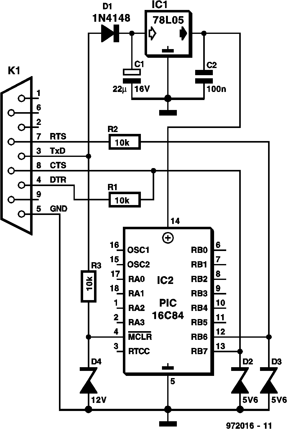
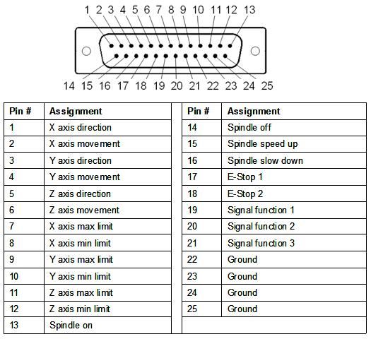
If you want to use the example with a DB25, simply replace the pin numbers of the connector according to the conversion table below. P13 P12 P11 P10 P15 GND GND P17 P16 P1 P14 P9 P8 P7 P6 P5 P4 P3 P2 VDD GND GND 5V KL-DB25 N.C sig + – sig + – sig + – Wall Plug P/S 5VDC Current MicroStep KLD driver PUL+ PUL-DIR+ DIR-ENA+ ENA-A+ A-B+ B-VCC GND Current.
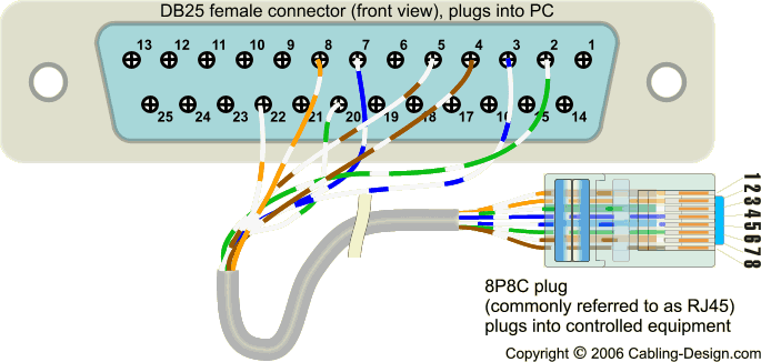
Figure 2 is the wiring scheme for the plug side of an RJ connector in accordance with TB standards. The TB standard is the most commonly used.
The wiring diagram is shown with the “hook clip” on the underside.RS serial cable pinout informationTech Stuff – RS Cables and Wiring