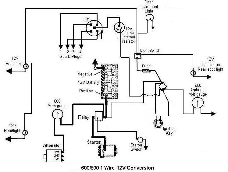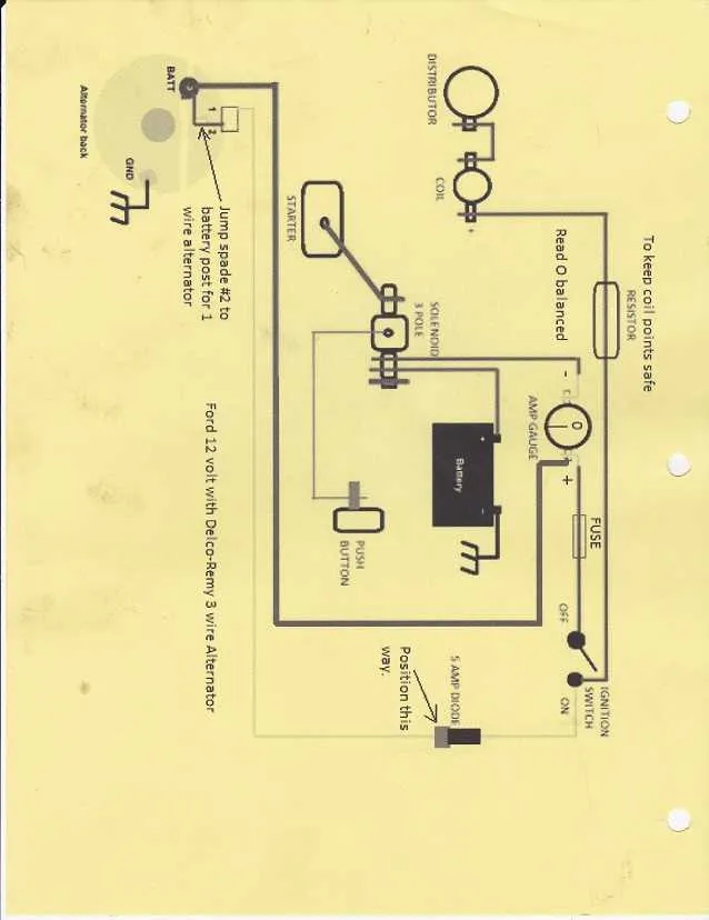
To achieve optimal performance in the 8N agricultural machine, ensure the power system is upgraded to a 12-unit current configuration. This involves replacing the original generator with a compatible alternator and installing a new regulator designed for the higher current flow.
Key connections include linking the battery’s positive terminal directly to the starter solenoid and ensuring a secure ground to the chassis. The ignition switch must be connected to the coil via the correct gauge cable to maintain stable spark delivery during operation.
Use a fused link rated at 20 amps between the main power source and the fuse block to protect the electrical components from overloads. The lighting circuits, including headlights and taillights, require wiring that supports the increased current without voltage drop, ideally using at least 14-gauge wire.
Proper identification of each terminal on the starter motor, ignition coil, and alternator is critical to prevent damage and ensure reliable startup and running conditions under field work.
12 Volt Electrical Layout of the 8N Model
Use a fused main line from the battery positive terminal to the ignition switch to protect the system against overloads. The starter solenoid should be connected directly to the battery and controlled by the ignition switch output.
Ensure the generator output wire is securely fastened to the voltage regulator’s input terminal, as this connection stabilizes the charging function. The regulator’s ground must be clean and firmly attached to the chassis to prevent erratic behavior.
Connect the ammeter between the battery positive and the regulator output to monitor current flow properly. Headlamp circuits require a switch fed from the ignition source with the proper gauge wire to handle the load without voltage drop.
The negative battery cable should be connected to the engine block, providing a solid ground return path to all electrical components. Replace any corroded terminals or frayed leads to ensure reliable performance.
Refer to color codes: red wires typically indicate power lines, green or brown are grounds, and yellow denotes lighting circuits. Follow these conventions to avoid confusion during maintenance or upgrades.
Understanding the 12 Volt Conversion Process on 8N Ford Tractor
Start by replacing the original 6-volt generator with a compatible 12-volt alternator or generator designed for this upgrade. Ensure the new charging unit matches the mounting points and pulley size to avoid mechanical adjustments. Swap the original regulator with a 12-volt compatible voltage regulator to maintain proper charging levels and prevent battery damage.
Upgrade the battery to a 12-volt type with sufficient cold-cranking amps to support the increased electrical load. Replace all bulbs and sockets with components rated for 12 volts to avoid premature failure or dim lighting. Check all connectors and terminals for corrosion and replace any wiring that cannot safely handle the increased electrical current.
Modify the ignition coil by selecting a coil designed for a 12-volt system, which provides proper resistance and prevents coil burnout. Replace the starter solenoid and any associated relays with units rated for 12 volts to ensure reliable engine starts. Re-route and secure all cables using correct gauge sizes, typically 14 to 10 AWG, depending on circuit length and load, to prevent voltage drop and overheating.
Finally, test the entire electrical system thoroughly with a multimeter under load conditions to confirm correct operation and consistent charging output. Proper grounding of the engine block and chassis is crucial to maintain circuit integrity and prevent electrical noise or failures.
Step-by-Step Guide to Installing the 12V Electrical System on an 8N Model

Begin by disconnecting the battery to ensure safety during the process. Identify the positive lead from the battery and connect it to the starter solenoid’s main terminal. Use a heavy gauge cable to handle the current load effectively.
Next, attach the ignition switch wire to the solenoid’s small terminal marked “S.” This connection controls the activation of the starter motor.
Locate the generator output post and connect a wire leading to the voltage regulator’s input. This regulator stabilizes the charging output.
Ground the regulator firmly by attaching its chassis terminal to the tractor’s frame with a clean, bare metal surface.
Connect the regulator’s output terminal to the battery’s positive post, ensuring proper current flow for battery charging.
Run a wire from the battery negative terminal to the engine block and frame to establish a solid ground return path.
Install the fuse or circuit breaker inline on the positive battery cable close to the battery terminal to protect the circuit from overloads.
Wire the lighting system by connecting the headlight leads to the light switch, then to the battery positive terminal via the fuse.
Test all connections by turning the ignition key to the “ON” position; the instrument lights and charging indicator should illuminate.
Verify starter engagement by activating the starter; the engine should crank without hesitation.
Finish by securing all cables away from heat sources and moving parts using clamps or ties to prevent damage or shorts.
Troubleshooting Common Issues in 8N 12V Electrical Systems
Start by verifying the battery connections; corrosion or loose terminals cause most power delivery problems. Use a multimeter to check voltage levels across the battery posts and key connection points.
- Check Ground Connections:
- Ensure the engine block and chassis grounds are clean and tight.
- Rust or paint layers under grounding straps reduce conductivity.
- Inspect the Starter Circuit:
- Test the solenoid by bypassing with a jumper wire to verify starter operation.
- Measure voltage drop across starter cables during cranking; excessive drop indicates cable degradation.
- Examine the Charging System:
- Use a test light or voltmeter to verify the generator output at various engine speeds.
- Check the regulator connections and ensure the correct polarity and secure mounting.
- Test Lighting Circuits:
- Look for burnt fuses or blown bulbs as a cause of dim or non-functioning lamps.
- Verify switch continuity with a multimeter.
- Inspect Harness Integrity:
- Look for brittle insulation or exposed wires prone to short circuits.
- Check connectors for corrosion and reseat or replace if necessary.
Regular maintenance of terminals and cables extends system reliability and reduces troubleshooting time.