Ensure seamless power continuity by implementing a reliable control mechanism that automatically redirects energy flow between the primary and backup supplies. Such systems must be wired with precision, prioritizing the correct sequence of load disconnection and reconnection to prevent damage and maintain operational safety.
Critical elements to focus on include the correct integration of input lines from the main grid and standby generators, along with clear labeling of the relay contacts responsible for switching actions. Pay special attention to interlocks that avoid simultaneous engagement of both power sources, minimizing risk of electrical faults.
Design layouts often feature a central controller coordinating the sequence and timing, complemented by contactors and sensors monitoring voltage presence. Accurate wiring practices and adherence to manufacturer specifications are essential to achieve smooth and fail-safe transitions.
Control System Layout for Power Source Selection

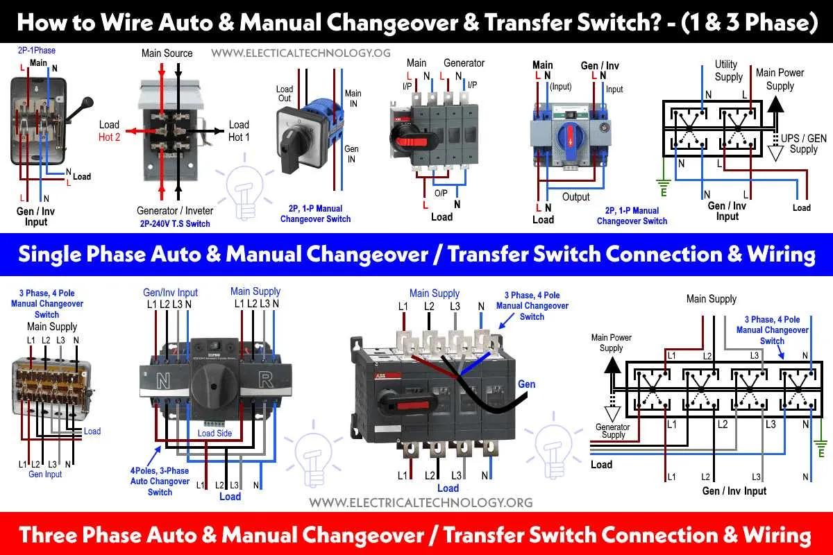
Ensure the design includes a clear representation of the main utility line, the backup generator feed, and the load connection. The primary circuit breaker should be positioned before the main input to protect against faults. Incorporate a contactor or relay arrangement to enable seamless switching between sources without interrupting power supply.
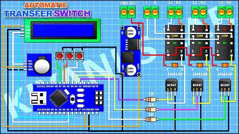
Include an interlock mechanism to prevent simultaneous connection of both feeds, avoiding backfeed risks. Control wiring must show the signal path from sensing devices that detect utility failure and trigger the generator startup sequence. Integrate a delay timer in the control path to allow stable source changeover and prevent rapid cycling.
Label all control points such as voltage sensing inputs, motorized actuator controls, and override manual operation clearly. Grounding connections must be explicitly shown to comply with safety standards. Use standardized electrical symbols for breakers, relays, and sensors to enhance readability and reduce misinterpretation during installation and maintenance.
Wiring Connections for Load and Power Sources
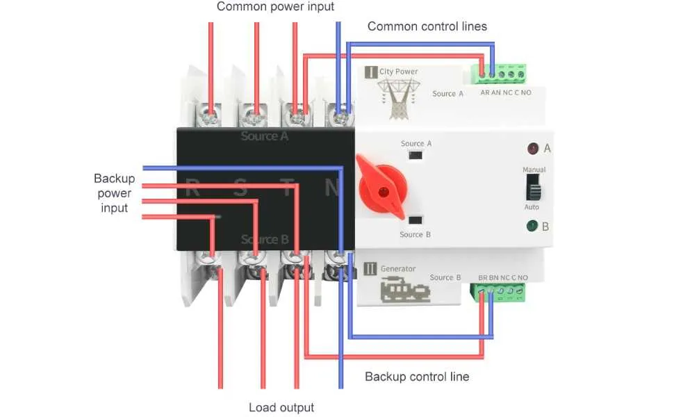
Connect the main power feed to the designated input terminals rated for the system’s voltage and current capacity. Use appropriately sized conductors based on the full load amperage, ensuring compliance with NEC or local electrical codes.
Link the secondary power source to its dedicated input points, verifying polarity and phase alignment when applicable. Employ separate circuit protection devices for each power line to prevent backfeeding and facilitate safe isolation.
Ensure the load output terminals are wired with cables rated for continuous operation at the expected load current. Use secure, torque-specified connections to minimize resistance and heat buildup.
Ground all metallic enclosures and neutral points according to grounding standards to avoid potential faults and enhance operational safety. Confirm bonding continuity before energizing the system.
Label all wiring clearly to identify source inputs and load outputs, simplifying maintenance and troubleshooting. Use durable markers or heat-shrink labels resistant to environmental factors.
Test each connection for tightness and insulation resistance prior to system commissioning. Verify the absence of voltage between isolated terminals to prevent unintended energization.
Steps to Interpret Control Logic in the Diagram

Begin by identifying the primary power sources and their sequence of operation. Trace the control signals from the main controller to relays or contactors, noting the conditions that trigger each state change. Focus on the logic gates or relay coils represented, understanding their role in enabling or disabling power paths.
Examine interlocks and safety features by locating normally closed and normally open contacts; these prevent undesired transitions. Check for auxiliary contacts that provide feedback loops or status indications, which clarify the operational flow.
Map timing elements such as delay relays or timers, observing their set intervals and how they influence the activation order. Confirm the logic that prioritizes source selection and the criteria for load transfer or isolation.
Follow the flow of control voltage lines, differentiating between control and power circuits. Verify grounding points and protective devices integrated into the control logic for fault prevention.
Document each component’s function within the sequence, cross-referencing symbols with legend keys. This systematic approach ensures accurate interpretation and troubleshooting capability.
Troubleshooting Common Wiring Issues Using the Schematic
Start by verifying that all power sources are properly connected and that the main lines correspond to the correct input terminals. Incorrect source alignment is the most frequent cause of malfunction.
- Check continuity between the load and each power input using a multimeter. Interruptions indicate breaks or loose connections.
- Inspect grounding connections carefully. Poor grounding can cause erratic operation or failure to transfer power.
- Confirm correct relay coil wiring as per the layout to ensure proper switching action. Reverse polarity or swapped leads prevent activation.
- Look for short circuits between phase and neutral lines by measuring resistance. Values close to zero indicate faults requiring isolation and repair.
- Verify control signals at the control module connectors. Incorrect wiring here results in failure to initiate changeover.
Use the schematic’s reference points to map each conductor and ensure consistency throughout the setup. Mark wires during inspection to avoid overlooking any connections.
- Label wires according to the schematic codes.
- Replace any damaged or corroded terminals immediately.
- Retighten all screw terminals to manufacturer torque specifications.
Systematic cross-checking against the layout reduces troubleshooting time and prevents repeated faults caused by wiring errors.