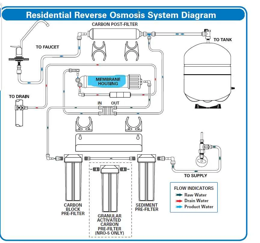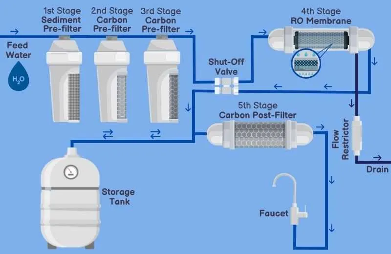
To optimize water purification, begin with a detailed schematic of the reverse osmosis assembly, highlighting key stages such as pre-filtration, high-pressure pumping, membrane separation, and post-treatment. Accurate placement of sediment and carbon filters ensures removal of large particles and chlorine, protecting the membranes from damage.
Pressure regulation is critical; include a booster pump with adjustable settings to maintain ideal flow rates and pressure levels, typically between 40 and 80 psi. This prevents membrane fouling and maximizes throughput. Incorporate flow restrictors immediately after the membrane to sustain pressure balance and control wastewater discharge.
Water flow paths must be clearly marked to track raw input, permeate output, and reject water routes. Integration of a permeate storage tank with a float valve improves system responsiveness and maintains consistent purified water supply. Monitoring points for pressure gauges and conductivity sensors provide essential feedback for maintenance and performance evaluation.
Proper component arrangement enhances efficiency and ease of service. Positioning valves and quick-connect fittings in accessible locations minimizes downtime during filter changes or membrane replacements. Implementing automated flushing mechanisms can prolong membrane life by reducing scaling and biofouling risks.
RO Setup Layout
To optimize the reverse osmosis assembly, position the main components in the following sequence for maximum efficiency and ease of maintenance:
- Pre-filtration unit: Install a sediment filter and activated carbon filter to remove large particles, chlorine, and organic contaminants that can damage membranes.
- High-pressure pump: Place immediately after pre-filters to ensure stable feed water pressure, ideally between 150-300 psi for residential units.
- Membrane housing: Use a vertical or horizontal pressure vessel with a high rejection polyamide membrane rated for at least 98% salt removal.
- Post-treatment: Include a UV sterilizer or remineralization cartridge to enhance water quality and taste.
- Storage tank: Position close to the outlet for minimized pressure loss and faster dispensing.
- Flow restrictors and check valves: Integrate to maintain proper flow rates and prevent backflow, ensuring membrane longevity.
Ensure all tubing uses food-grade materials, with quick-connect fittings for straightforward servicing. Arrange components to minimize bends and length of tubing to reduce pressure drop and contamination risk.
- Feed water should pass sequentially through each stage without bypass.
- Include pressure gauges before and after the membrane housing for monitoring performance.
- Install an automatic flush valve to prevent membrane fouling in high-TDS applications.
Key Components and Their Functions in RO Setup

The feed water pump is essential for maintaining the required pressure, typically between 150 and 300 psi, to drive water through the membrane. High pressure ensures efficient separation of impurities.
Pre-filters, usually sediment and carbon types, remove particles and chlorine to protect the membranes from damage and fouling, extending their lifespan by up to 50%.
RO membranes act as the core filtration unit, selectively allowing water molecules to pass while blocking up to 99% of dissolved salts, bacteria, and organics. Thin-film composite membranes are preferred for their high rejection rates and durability.
The flow restrictor maintains a consistent flow rate on the membrane’s concentrate side, optimizing recovery rates around 75% without compromising membrane integrity.
A pressure vessel houses the membranes and withstands operational pressure, typically constructed from fiberglass or stainless steel to resist corrosion and ensure longevity.
Post-filters, often activated carbon, polish the purified water by removing residual tastes and odors, ensuring high-quality output suitable for consumption or industrial use.
Automatic shut-off valves halt water flow once the storage tank is full, preventing overflow and conserving water. This valve activates based on pressure differences.
A storage tank holds treated water under air pressure, allowing immediate delivery on demand. Typical capacity ranges from 3 to 14 gallons depending on application scale.
Flow meters or conductivity meters monitor permeate and concentrate streams, providing real-time data for maintenance and performance optimization.
Step-by-Step Flow of Water Through an RO Process
Begin by pre-filtering raw water to remove large particles, chlorine, and sediments that could damage the delicate membrane. This stage typically uses a sediment filter and activated carbon.
Next, pressurize the filtered water using a pump to force it through the semi-permeable membrane. Operating pressure usually ranges between 40 and 80 psi, depending on feed water quality.
At the membrane stage, pure water molecules pass through, while dissolved salts, bacteria, and organic contaminants are retained and flushed away as concentrated brine.
Following membrane filtration, water flows into a storage tank, where it accumulates until needed, ensuring steady availability.
Before consumption, the stored water passes through a final polishing filter, often a carbon post-filter, to improve taste and remove any residual odors.
Periodically, the unit performs an automatic flush to clean the membrane surface, reducing fouling and extending operational lifespan.
Each stage demands precise maintenance–replace pre-filters every 6 to 12 months, monitor membrane condition annually, and sanitize storage to maintain optimal water quality.
Common Issues Identified Through RO Flowcharts and Troubleshooting
Check for membrane fouling first; a sharp decline in permeate flow or rise in differential pressure typically indicates clogging by particulates or biofilm. Regular cleaning protocols using chemical agents like citric acid or sodium hypochlorite are essential to restore performance.
Inspect feedwater pressure at the inlet–pressure drops below 3 bar often reduce rejection efficiency and output. Verify pump functionality and pre-filter condition to maintain optimal feed conditions.
Monitor salt rejection rates; values falling under 95% suggest membrane damage or compaction. Replace membranes when physical integrity is compromised, as cleaning cannot restore selective permeability.
Check for leaks in tubing and fittings, especially around high-pressure components. Even minor leaks cause pressure loss and reduced recovery rates. Use pressure gauges at critical points to detect anomalies.
Evaluate concentrate flow rates; excessive recovery beyond 75% raises scaling risks. Adjust flow controllers and ensure antiscalant dosing is accurately calibrated to prevent deposit formation.
Assess conductivity sensors and controllers for calibration drift. Incorrect readings may lead to improper system adjustments, affecting water purity. Calibrate sensors monthly to maintain accuracy.
Confirm that automatic flush cycles occur as scheduled. Skipping these intervals promotes membrane fouling and shortens lifespan. Integrate reliable timers and alarms to enforce maintenance routines.