Follow this precise layout to ensure optimal tension and alignment of the engine’s accessory loop. Proper installation prevents premature wear on pulleys and maximizes the lifespan of all rotating components.
Accurate path tracing for the continuous drive loop is crucial when replacing or inspecting the system. Misrouting can cause slipping, noise, or damage to the alternator, power steering pump, and air conditioning compressor.
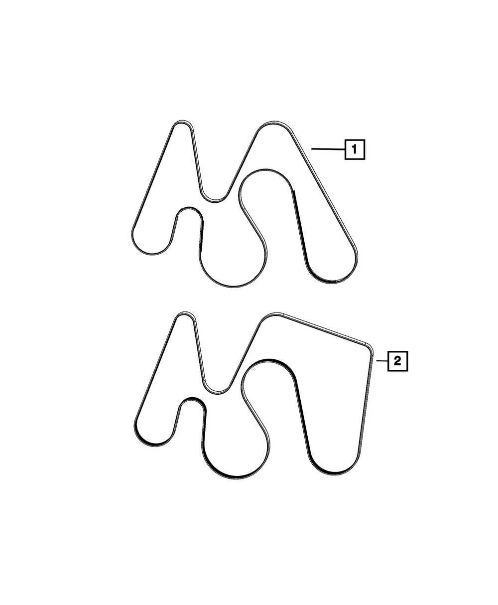
Use the factory-approved reference for the multi-groove drive line to confirm exact pulley engagement order and correct routing direction. Visualizing the correct path before installation reduces downtime and eliminates guesswork.
Routing Layout for Accessory Drive

For accurate installation of the engine’s accessory drive loop, reference the specific routing map that details the path around the crankshaft pulley, alternator, power steering pump, and air conditioning compressor. Ensure tensioner placement corresponds to the manufacturer’s specifications to maintain optimal tension and avoid premature wear.
Identify each component’s position relative to the pulleys by matching the configuration to the provided schematic for your engine model. Use a tension gauge to verify the correct preload after fitting the loop around all pulleys, especially near the idler and tensioner wheels. Incorrect alignment or slack can cause slippage, noise, and reduced efficiency.
Follow torque values for all mounting bolts during reassembly to prevent misalignment. Double-check routing for interference with moving parts or wiring harnesses. Confirm smooth rotation of all pulleys by manually spinning them before engine start to detect any binding or misrouting issues early.
Identifying Key Components in a 6.7 Serpentine Belt Layout

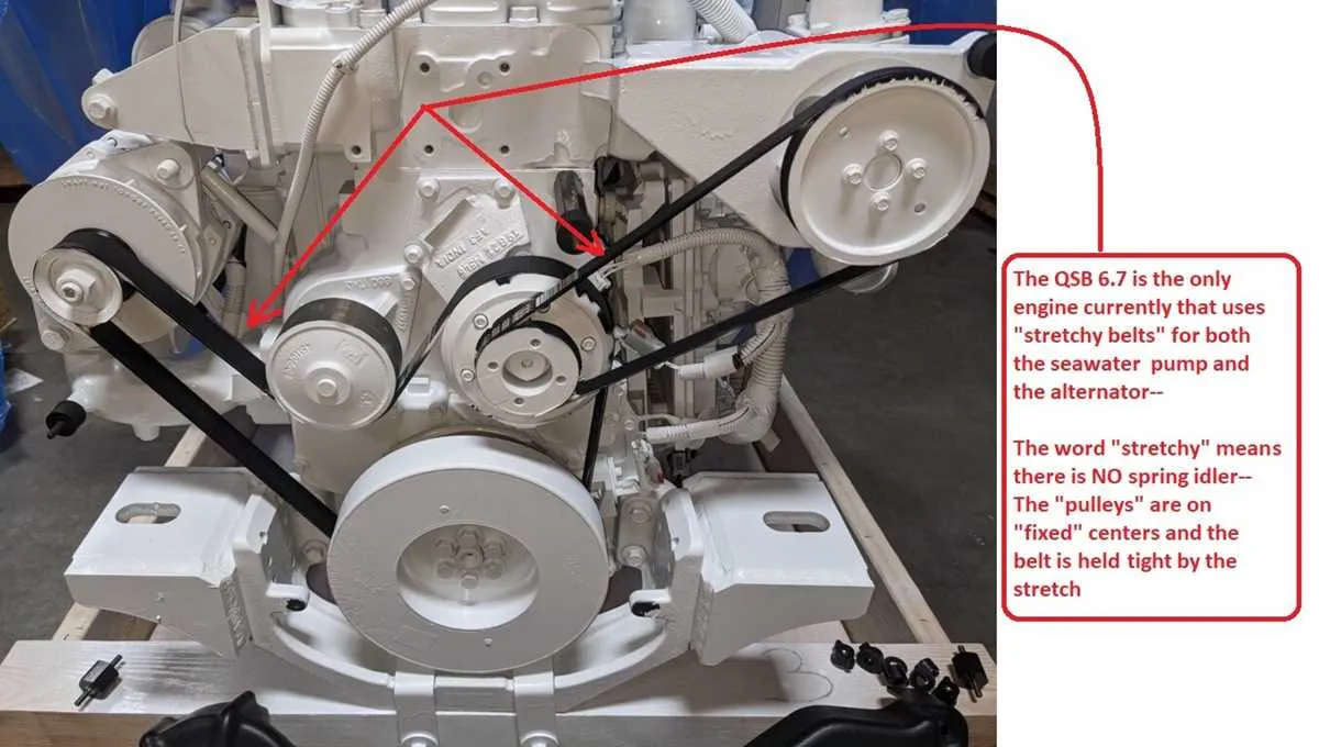
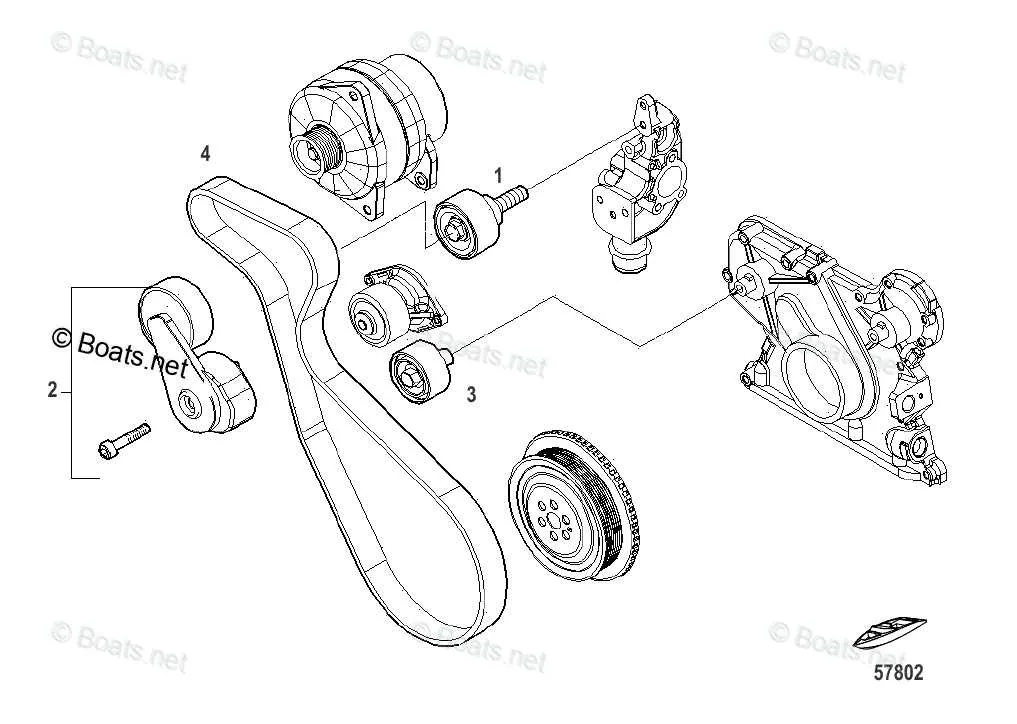
Locate the tensioner pulley first, as it maintains the proper tension on the drive loop and ensures smooth operation. The idler pulley follows, guiding the path without load transfer. The crankshaft pulley is the primary driver, transmitting engine power to all accessories.
Next, identify the alternator pulley responsible for electrical charging, the water pump pulley managing coolant circulation, and the air conditioning compressor pulley controlling the HVAC system. Each of these must be correctly aligned to prevent premature wear or slippage.
| Component | Function | Typical Position |
|---|---|---|
| Tensioner Pulley | Maintains tension in the drive system | Usually near the front, adjustable arm |
| Idler Pulley | Guides routing path without power transfer | Between accessory pulleys to adjust routing |
| Crankshaft Pulley | Main power source driving the loop | Lowest pulley connected to engine crankshaft |
| Alternator Pulley | Generates electrical power | Upper section, driven by main loop |
| Water Pump Pulley | Circulates coolant through engine | Near center, aligned with engine cooling |
| AC Compressor Pulley | Operates air conditioning system | Typically on the side, driven by accessory loop |
Confirm correct pulley alignment and tension adjustment before operation to avoid damage. Use a routing schematic specific to the engine model for precise component identification and troubleshooting.
Step-by-Step Guide to Replacing a 6.7 Serpentine Belt Using the Diagram
Begin by locating the routing schematic on your vehicle or service manual. This illustration is essential for proper installation and prevents misalignment.
Disconnect the negative battery terminal to ensure safety during the process.
Use a wrench or serpentine tool to relieve tension on the tensioner pulley. Rotate it in the specified direction to slacken the old loop.
Slide off the worn drive loop carefully from the pulleys, noting the routing path. Avoid forcing or damaging surrounding components.
Compare the new replacement with the old one to confirm correct length and rib alignment.
Refer to the routing schematic again and begin threading the fresh loop around the crankshaft, alternator, water pump, and other pulleys following the precise path.
Apply tension by releasing the tensioner pulley slowly, ensuring the new drive loop seats properly on all grooves without slipping.
Double-check alignment by spinning the accessory pulley by hand; there should be no slipping or misalignment.
Reconnect the battery terminal and start the engine briefly to observe operation. The loop should run smoothly without noise or wobble.
Proper adherence to the routing guide guarantees optimal performance and longevity of the component system.
Troubleshooting Common Routing Issues
Ensure proper alignment of the drive loop to prevent premature wear or noise. Misrouted or twisted loops cause slippage and reduce component lifespan.
- Inspect tensioner pulley position–incorrect tension often leads to squealing or loss of grip.
- Verify all pulleys spin freely; seized or damaged rollers disrupt smooth operation and can cause system failure.
- Check for missing or reversed loop path around accessories such as the alternator, water pump, and power steering pulley.
- Replace worn guides or idlers that may allow the loop to slip off or chatter during engine operation.
Follow these steps to resolve common issues:
- Use a routing reference specific to your engine variant to confirm correct loop positioning.
- Apply tension gradually, ensuring the loop sits squarely in each pulley groove.
- Listen for abnormal noises after installation–squeaks or chirps often indicate improper routing or tension.
- Perform a visual check at operating temperature; expansion can alter tension and alignment.
Neglecting proper path and tensioning results in accelerated degradation and potential accessory malfunction. Systematic verification prevents costly repairs and downtime.