
Directv MDU Installation Diagram is a visual representation of the setup required for DirecTV to be installed in a Multiple Dwelling Unit (MDU). MDU refers to a building or housing complex that has multiple units or apartments. Installing satellite TV in such buildings can be challenging due to the complex infrastructure and the need for individual access to the service in each unit.
This diagram provides a comprehensive overview of the equipment and connections needed for Directv installation in MDUs. It showcases the key components such as the satellite dish, multiswitches, and distribution equipment, which are necessary for broadcasting the signal to multiple units within the building.
Directv MDU installation requires coordination between the building owner, the satellite TV provider, and the residents. The diagram reflects the typical setup, where a satellite dish is installed on the roof or balcony of the building, with multiple cables running from it to a central distribution point.
In the central distribution point, the signal is distributed to each unit via a multiswitch or a combination of multiswitches. Each unit is then equipped with a set-top box or a receiver to decode the signal and provide access to the Directv channels and services.
What is a MDU Installation Diagram and How Does it Work?
An MDU installation diagram refers to a visual representation of the setup and configuration of a DirecTV system in a multi-dwelling unit (MDU) such as an apartment building or condominium complex. This diagram outlines the process of connecting satellite dishes to receivers and distributing the signal to individual units within the MDU.
The diagram typically includes details such as the location of the main satellite dish, the type of distribution equipment used, the routing of cables and wires, and the placement of receivers in each unit. It provides a clear overview of how the DirecTV system is integrated into the MDU infrastructure, ensuring efficient signal distribution and optimal reception for all residents.
Components of a MDU Installation Diagram:
- Main satellite dish: This is the primary source of the DirecTV signal. It is usually located on the roof or a centralized area of the MDU.
- Distribution equipment: This includes components such as multi-switches, splitters, amplifiers, and coaxial cables. They help distribute the signal from the main dish to individual units.
- Receivers: Each unit within the MDU is equipped with a DirecTV receiver, which decodes the satellite signal and displays it on the resident’s television.
- Cabling and wiring: The diagram shows the routing of cables and wires from the main dish to the distribution equipment and then to each unit. This ensures that the signal is properly transmitted without any loss or interference.
Overall, an MDU installation diagram serves as a guide for technicians and installers to set up DirecTV systems in MDUs. It helps ensure that all necessary components are properly connected and positioned for optimal signal reception, allowing residents in the MDU to enjoy their DirecTV services without any interruptions or issues.
Understanding the Basics of MDU Installation Diagrams
MDU (Multi-Dwelling Unit) installation diagrams are essential tools for technicians working on installing and setting up Directv systems in apartment buildings or other multi-unit housing complexes. These diagrams provide a visual representation of how the system should be installed and connected, helping technicians to understand the specific requirements and configurations for each unit within the building.
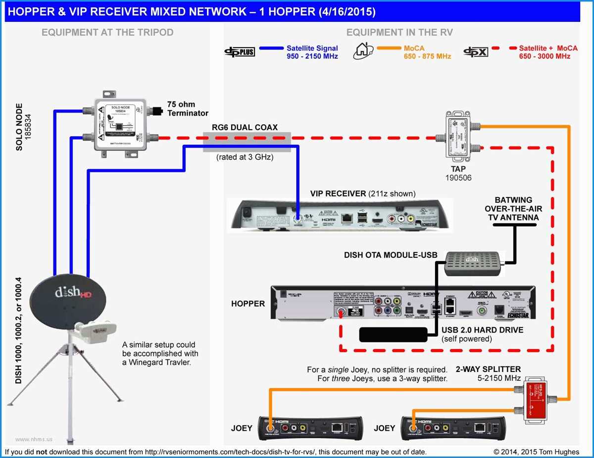
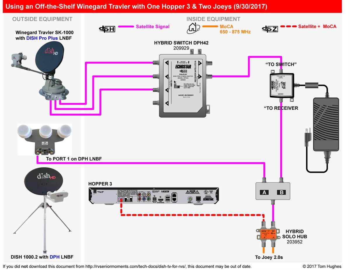
Components: A typical MDU installation diagram will include various components such as satellite dishes, multiswitches, cables, connectors, and receivers. The diagram will show the placement of the satellite dishes on the roof or the side of the building, along with the necessary cables and connectors to connect each unit to the dish. It will also indicate the location of the multiswitches, which are used to distribute the satellite signals to multiple receivers.
Wiring Layout: The installation diagram will provide a detailed layout of the wiring within the building, showing how the cables should be routed from the satellite dishes to the multiswitches and then to the individual units. This includes information about the size and type of cables to be used, as well as any necessary splitters or amplifiers. The diagram will also indicate the placement of wall plates and outlets in each unit for connecting the receivers.
Signal Flow: Understanding the flow of the satellite signals is crucial for a successful installation. The diagram will clearly show the direction of the signals, starting from the satellite dish, passing through the cables and multiswitches, and finally reaching the receivers in each unit. Technicians can use this information to ensure that the signals are properly distributed and that there are no signal losses or interruptions along the way.
Unit Configuration: Each unit within the MDU may have different requirements and configurations. The installation diagram will provide specific instructions for each unit, including the number of cables and connectors needed, the placement of the receivers, and any additional equipment that may be required. This ensures that each unit receives the appropriate satellite signal and can access the desired channels and services.
Overall, MDU installation diagrams are invaluable resources for technicians working on Directv installations in multi-unit buildings. They provide a clear and concise guide to the installation process, helping to ensure that each unit within the MDU receives a reliable and high-quality satellite signal.
The Importance of MDU Installation Diagrams for DirecTV
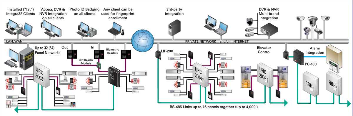
MDU installation diagrams play a crucial role in the successful installation and setup of DirecTV services in multi-dwelling unit (MDU) buildings. These diagrams provide a detailed visual representation of the network infrastructure, equipment placement, and wiring requirements necessary to deliver high-quality television signals to each unit in the building.
One of the key benefits of MDU installation diagrams is that they ensure consistency and uniformity in the installation process. By following a standardized diagram, installers can avoid mistakes and errors that may lead to signal loss or poor picture quality. This is especially important in MDU buildings where multiple units are connected to a single satellite dish or antenna.
The MDU installation diagram typically includes:
- A layout of the MDU building, indicating the location of the satellite dish or antenna on the roof or exterior of the building.
- The distribution system, which may include amplifiers, splitters, and coaxial cables that carry the signal from the dish or antenna to each unit.
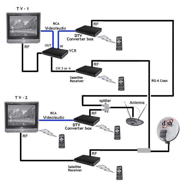
- The wiring configuration inside each unit, including the placement of the receiver, TV, and other equipment.
Having a clear and detailed MDU installation diagram is crucial for installers to understand the requirements of the building and ensure a smooth installation process. It helps them determine the best routing of cables, the type and quantity of equipment needed, and any potential challenges they may encounter.
In addition to assisting installers, MDU installation diagrams also serve as a valuable resource for building owners, property managers, and maintenance personnel. They provide a reference point for troubleshooting and maintenance activities, ensuring that any issues can be addressed quickly and efficiently.
In conclusion, MDU installation diagrams are an essential tool for DirecTV installers and building owners alike. They ensure accurate and consistent installations, improve signal quality, and simplify troubleshooting and maintenance tasks. By providing a clear visual representation of the network infrastructure, these diagrams contribute to a better viewing experience for residents in MDU buildings.
Components of a Directv MDU Installation Diagram

A Directv MDU (Multi-Dwelling Unit) installation diagram shows the various components and connections required to distribute satellite TV signals to multiple units within a building. These diagrams are used by technicians to plan and execute installations efficiently.
Some of the key components that are typically included in a Directv MDU installation diagram are:
- Satellite Dish: The satellite dish is the starting point of the installation and is responsible for receiving signals from the satellite. It is usually mounted on the rooftop or the side of the building.
- LNB: The Low Noise Block (LNB) is attached to the satellite dish and amplifies the received signals. It also converts the high-frequency signals to a lower frequency for easier transmission.
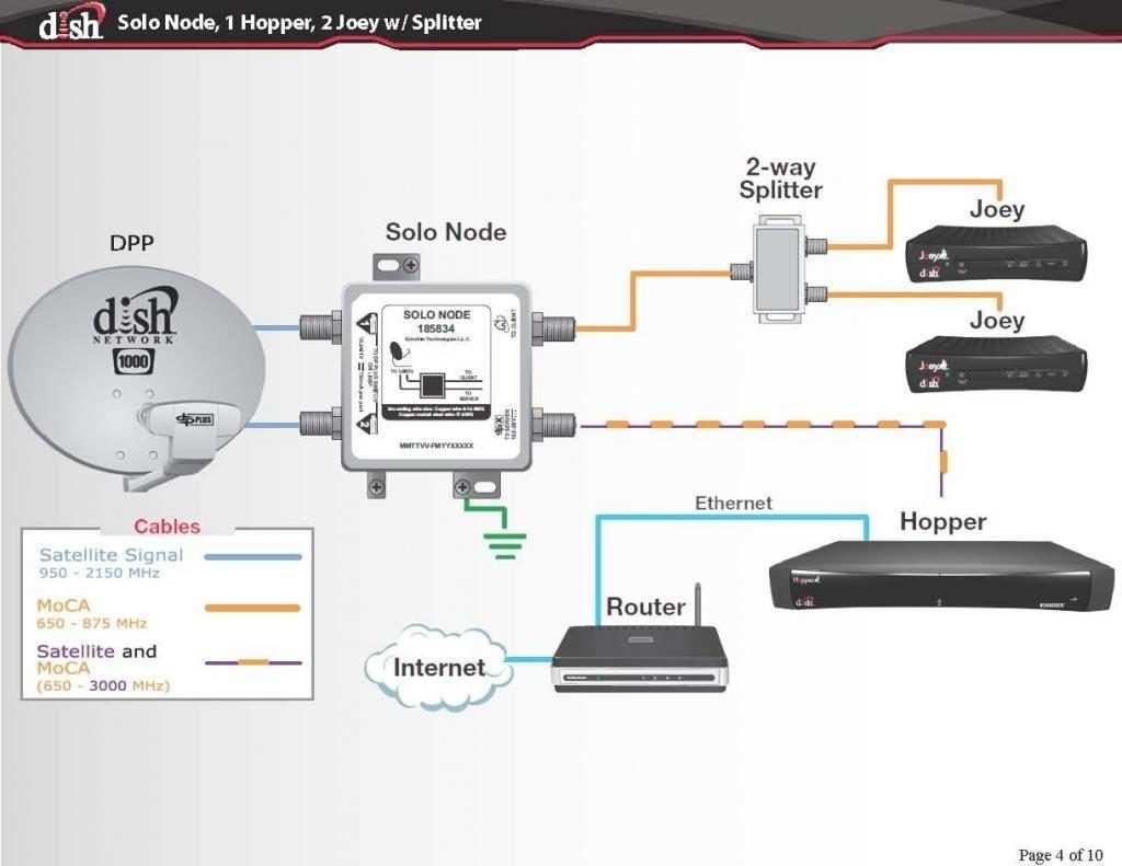
- Satellite Switches: In an MDU setup, satellite switches are used to distribute the satellite signals to individual units. These switches allow for the connection of multiple receivers and enable each unit to select and receive the desired channels.
- Coaxial Cables: Coaxial cables are used to transmit the satellite signals from the dish, through the switches, and into each individual unit. These cables are designed to handle the high-frequency signals and ensure minimal signal loss.
- Splitters: Splitters are used to split the satellite signal into multiple feeds, allowing for the distribution to different units. These devices can split the signal into two, four, or more outputs, depending on the number of units in the MDU.
- Signal Amplifiers: In cases where there are long cable runs or multiple units with weaker signal reception, signal amplifiers may be used to boost the strength of the satellite signals. These amplifiers ensure a reliable signal transmission throughout the MDU.
- Receiver/TV Connections: Each individual unit will have a receiver or TV connected to the satellite system. These connections typically involve coaxial cables running from the satellite switch to the receiver/TV, allowing for the reception of the selected channels.
- Grounding System: A proper grounding system is an essential component of any satellite installation. It helps protect the equipment from power surges and ensures the safety of the residents. A grounding block is often included in the MDU installation diagram.
By following a Directv MDU installation diagram and properly implementing these components, technicians can ensure a reliable and efficient satellite TV distribution system within multi-dwelling units.
Step-by-Step Guide to Creating a Directv MDU Installation Diagram
Creating a Directv MDU installation diagram is an important step in ensuring a successful installation process. This diagram serves as a visual representation of the proposed layout and connectivity of the Directv system within the MDU (multi-dwelling unit). Here is a step-by-step guide to help you create an accurate and comprehensive installation diagram.
Step 1: Gather all essential information
Start by collecting all the necessary information for the installation diagram. This includes the number of units in the MDU, the location of the equipment room, the path of the cable, and any specific requirements or limitations for the installation. It is crucial to have a clear understanding of the MDU’s layout and the desired placement of the Directv equipment.
Step 2: Identify the equipment room
Determine the location of the equipment room where the main Directv equipment will be installed. This could be a designated room or an appropriate space within the MDU. Note this on the diagram as it will be the central hub for connecting all the units within the MDU to the Directv system.
Step 3: Map out the cable path
Next, carefully plan the route of the cable from the equipment room to each individual unit. Consider any obstacles or restrictions that may affect the cable installation, such as walls, floors, or other utilities. Clearly indicate the cable path on the diagram to help technicians during the installation process.
Step 4: Determine the placement of equipment
Based on the layout and requirements of the MDU, decide where the receivers, switches, and other necessary equipment will be placed within each unit. Note down the specific locations on the diagram to ensure accurate installation and proper connectivity.
Step 5: Consider signal distribution
Take into account how the signal will be distributed throughout the MDU. Decide whether a centralized or decentralized system would be more suitable and indicate this on the diagram. Additionally, consider the signal strength and quality in each unit and plan any necessary amplifiers or boosters accordingly.
Step 6: Add labels and details
Lastly, add labels and additional details to the installation diagram to provide clarity and ease of use for the technicians. Include unit numbers, cable lengths, connection types, and any other relevant information that will contribute to a smooth and efficient installation process.
By following this step-by-step guide, you can create a comprehensive and accurate Directv MDU installation diagram. This diagram will serve as a valuable tool for technicians and help ensure a successful installation of the Directv system within the MDU.
Common Challenges and Solutions in MDU Installation Diagrams
When it comes to MDU installation diagrams for Directv, there are several common challenges that may arise. These challenges can make the process more complicated and require unique solutions. Here are some of the most common challenges and their solutions:
Limited Space:
In MDU environments, space is often limited, making it challenging to install the necessary equipment. The solution to this challenge is to carefully plan and optimize the use of available space. This may involve utilizing compact equipment or rearranging existing infrastructure to create more room.
Complex Wiring:
MDU installations often involve complex wiring setups due to the multiple units and floors involved. Ensuring that each unit receives the appropriate signal can be a challenge. To overcome this challenge, technicians must carefully design and label the wiring diagram, ensuring that each unit is correctly connected.
Individual Unit Customization:
Each unit within an MDU may have unique requirements, such as specific receiver configurations or individual channel preferences. The solution to this challenge is to create a flexible installation plan that allows for customization on a unit-by-unit basis. This can involve using modular components or programming options that cater to individual preferences.
Signal Interference:
In MDU environments, signal interference from neighboring units or external sources can affect the overall quality of the reception. To mitigate this challenge, technicians may need to implement signal amplification or isolation techniques. This can include using directional antennas or installing signal boosters where necessary.
Management and Maintenance:
MDU installation diagrams need to be accessible and easily understandable for future management and maintenance purposes. The solution to this challenge is to invest in proper documentation and organization. This can involve creating a comprehensive inventory of equipment, labeling all connections, and providing detailed diagrams that are easy to interpret.
Overall, MDU installation diagrams for Directv can be complex due to the unique challenges presented by multi-unit environments. However, with careful planning, customized solutions, and proper documentation, these challenges can be overcome, resulting in a successful installation process.
Tips for Optimizing DirecTV MDU Installation Diagrams
When it comes to DirecTV MDU installation diagrams, there are some tips that can help optimize the process and ensure a successful installation. By following these tips, you can minimize potential issues and improve the overall installation experience.
1. Clearly Label Components and Connections
One important tip for optimizing DirecTV MDU installation diagrams is to clearly label all components and connections. This includes labeling the satellite dish, switches, cables, and any other relevant equipment. Clear labels help ensure that technicians can easily identify and understand the different components and connections during the installation process.
2. Provide Detailed Information
Another tip is to provide detailed information in the installation diagrams. This includes specifying the exact placement of each component, the length and type of cables to be used, and any other relevant details. By providing detailed information, you can help eliminate confusion and ensure that the installation is done correctly.
3. Use Standard Symbols
Using standard symbols in the MDU installation diagrams can also help optimize the process. Standard symbols are recognized and understood by technicians, making it easier for them to interpret the diagrams accurately. This can help streamline the installation process and reduce the likelihood of errors or miscommunications.
4. Include a Legend
Including a legend in the installation diagrams is another useful tip. A legend provides a key for interpreting the symbols and labels used in the diagram. This can help technicians quickly understand the meaning of different elements and make the installation process more efficient.
5. Regularly Update the Diagrams
Lastly, it’s essential to regularly update the MDU installation diagrams to reflect any changes or updates in the system. As the technology and equipment evolve, it’s crucial to ensure that the diagrams accurately represent the current setup. Regularly updating the diagrams helps avoid confusion and ensures that technicians have the most up-to-date information.
By following these tips, you can optimize the DirecTV MDU installation process and improve the overall efficiency and accuracy of the installations. Clear labels, detailed information, standard symbols, a legend, and regular updates are all key elements for successful MDU installations.
Q&A:
What are MDU installation diagrams?
MDU installation diagrams, or Multi-Dwelling Unit installation diagrams, are visual representations of the DirecTV installation setup for apartment buildings or other multi-unit structures. They illustrate how satellite dishes, cables, and other equipment should be installed to provide satellite TV service to all units within the building.
Why is optimizing MDU installation diagrams important?
Optimizing MDU installation diagrams is important to ensure a smooth and efficient installation process. Well-optimized diagrams help technicians understand the layout and connectivity requirements, reducing errors and simplifying the installation process. This can save time, resources, and prevent the need for rework.
Who is responsible for optimizing MDU installation diagrams?
The responsibility for optimizing MDU installation diagrams typically falls on the DirecTV installation teams or technicians. They should work closely with project managers, engineers, and other stakeholders to ensure the diagrams accurately represent the installation requirements and facilitate a smooth installation process. Regular coordination and communication among the team members are essential for optimizing the diagrams effectively.