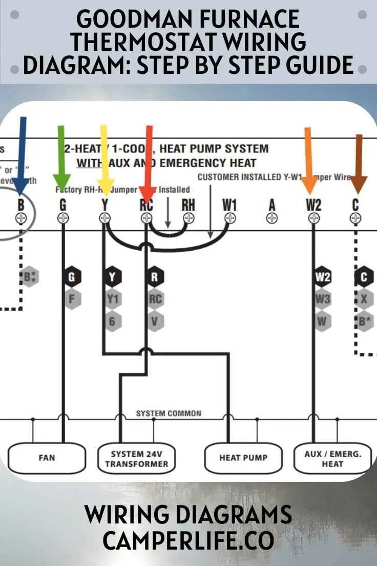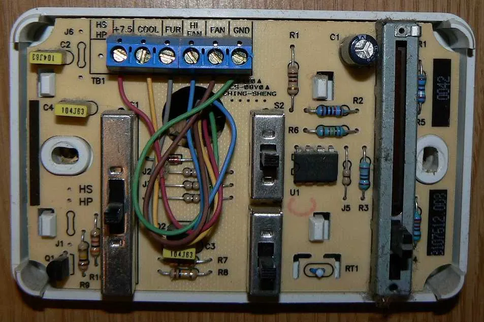
When dealing with a 3-wire temperature control setup, proper connections are essential for accurate functionality. The first step is identifying the three main terminals: the common terminal (C), the cooling terminal (Y), and the heating terminal (W). Begin by ensuring each wire is securely connected to its corresponding terminal on the control unit.
Step-by-step, here’s how to proceed:
First, connect the common terminal (C) to the neutral wire. This is critical for powering the control unit. Next, attach the cooling wire to the Y terminal. This ensures that the system engages the cooling process when the desired temperature exceeds the set threshold. Finally, connect the heating wire to the W terminal, which will trigger the heating mechanism when the temperature falls below the set point.
Important Considerations:
Always double-check the wiring against the control unit’s instructions. A misconnection can lead to malfunctioning or even damage to the components. Ensure that your power source is turned off before beginning any connections to prevent electrical hazards.
After all connections are made, test the system by adjusting the temperature settings and verifying that both heating and cooling elements respond correctly. If there is any malfunction, recheck each terminal for secure contact and proper wire placement.
Wiring the 3-Pin Temperature Control System
When connecting a 3-pin temperature control unit, ensure the following sequence for proper functionality: The first pin should be linked to the power supply, typically labeled as “C” or “Common.” The second pin corresponds to the cooling component, usually marked as “Y” or “Cool.” Finally, the third pin is connected to the heating element, often labeled as “W” or “Heat.”
Ensure all connections are tight and free from corrosion. Use the recommended gauge of cable for each pin to prevent overheating or short circuits. Check the unit’s specifications to verify the correct voltage for the power supply and avoid mismatched connections.
If the system includes a fan control, verify that the fan relay is appropriately wired to the cooling and heating components, depending on the mode selected. Testing should be done with the power off, and once connected, verify all components function correctly by cycling through heating and cooling modes.
For safety, always double-check connections with a multimeter to confirm no shorts exist before powering the system. It’s also essential to follow the manufacturer’s instructions for any additional setup or configuration specific to the model in use.
How to Identify the Three Wires in a Temperature Control System
To correctly identify the three essential connections in a temperature regulation unit, follow these specific steps:
- Locate the Control Unit: Open the housing where the device’s connections are made. You will see multiple terminals, typically marked for easy identification.
- Examine the Terminals: The key terminals are generally labeled as “C,” “R,” and “Y” or sometimes as “W,” “C,” and “R.” These correspond to different functions within the system.
- Common (C) Connection: This is the terminal responsible for the return path of electrical current. It is usually connected to the power supply ground.
- Cooling (Y or W) Terminal: This terminal controls the activation of the cooling component when temperature drops below the preset threshold. It is typically the shortest cable in length.
- Power (R) Terminal: This connection provides the necessary power to the system, often running directly from the power supply source.
Confirm the color coding: the “C” wire is often blue or black, the “R” wire tends to be red, and the “Y” or “W” wire is typically yellow or white. These colors can vary, so it’s important to cross-check with the user manual.
For safety, ensure the power is off before handling any connections. After confirming each wire, carefully secure them back into place, matching each terminal with the corresponding wire. Proper identification is crucial for the efficient operation of the system.
Step-by-Step Guide to Wiring a 3-Wire Temperature Control

Start by turning off all power sources to avoid electrical hazards. Locate the control panel or junction box where the device is installed.
Next, identify the three terminals–each corresponding to specific functions. The first is typically for the cooling component, the second for heating, and the third serves as the common or ground connection.
For the cooling connection, connect the wire from the cooling system to the terminal designated for cooling. Ensure the wire is securely attached using a screw or clamp to avoid loose connections.
Similarly, for heating, attach the heating system’s wire to the appropriate terminal. Check the polarity to ensure correct operation; incorrect wiring could damage components or cause malfunction.
The third terminal is where the common or ground wire should go. This is essential to complete the circuit and allow proper function of both heating and cooling modes.
After connecting the wires, double-check each one for firmness and security. Improper connections could lead to unreliable performance or system failure.
Finally, power the system back on and test the functionality of both heating and cooling settings. Ensure that the system responds correctly to the adjustments, verifying that each component is controlled as intended.
Troubleshooting Common Electrical Issues with 3-Pin Control Systems
If the system isn’t responding correctly, start by checking for loose or disconnected terminals. A loose connection can lead to intermittent performance or complete failure. Ensure that all the connectors are firmly attached to their respective terminals.
Next, verify the voltage supplied to the control unit. Inconsistent or insufficient voltage can cause malfunction or erratic behavior. Use a multimeter to check for the correct voltage at the designated input points, typically ranging from 12V to 24V, depending on the unit specifications.
Inspect the control board for any signs of damage, such as burnt components or discolored areas. Overheating or short circuits can damage the internal parts of the system, leading to failure. If any damage is found, replacing the control board might be necessary.
If there is no response from the system despite proper voltage, test the signal connections from the sensor to the control unit. A faulty sensor can lead to incorrect readings and improper operation. Ensure that the sensor is clean, connected securely, and not obstructed by debris.
In cases where the system operates intermittently, consider checking for ground faults. A poor ground connection can cause erratic behavior or complete failure to function. Ensure the ground is securely connected and free from corrosion or dirt.
Lastly, if the issue persists, replace the internal relay. These components can wear out over time, especially if the system is subjected to frequent switching cycles. A faulty relay can prevent the unit from activating or deactivating correctly.