For those troubleshooting or installing motor control systems, it’s critical to have a clear grasp of the wiring layout and how different components interact. The configuration of components like switches, power sources, and protection elements should follow specific standards to ensure both safety and efficiency.
Start by verifying that each control element is correctly connected to its respective power input. This step is fundamental in preventing short circuits or malfunctioning of the entire system. Pay attention to switches or relays designed to control current flow, ensuring they match the motor’s voltage and current specifications. Incorrect connections or mismatched components can lead to overheating or system failure.
Next, identify the contact points that activate the control mechanism. The control box usually houses these components, which need to be arranged properly to allow seamless operation. You should always double-check the wiring from the power source to the system’s control mechanism for signs of wear or corrosion that could interfere with performance.
Lastly, ensure that the ground connections are secure, and the overload protection is in place. These features are essential in maintaining a safe operational environment by preventing electrical faults from damaging the equipment. Proper grounding protects against accidental shocks or electrical fires.
Cooling System Circuit Schematic
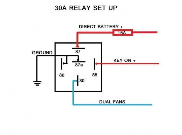
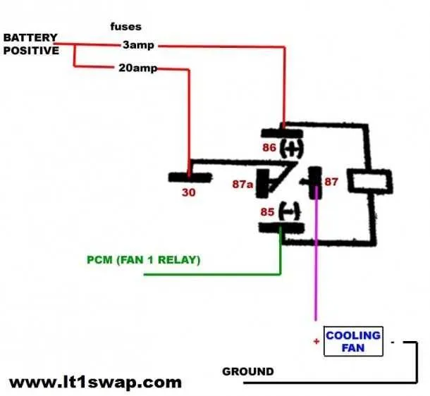
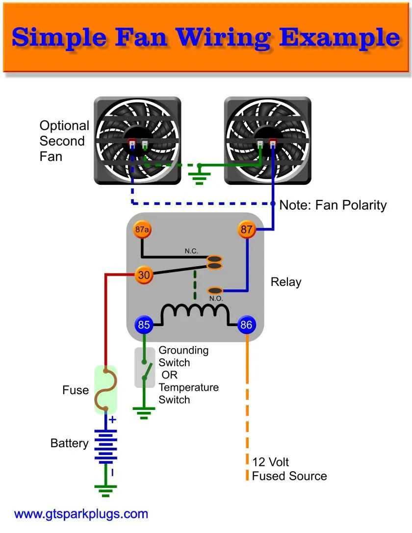
When working with a temperature control switch, it’s crucial to correctly wire the components to ensure smooth operation. The switch activates the motor, which in turn powers the ventilation mechanism once the engine reaches a certain heat threshold. The circuit typically includes a control unit, a thermal sensor, and a contact switch, each connected through conductive paths that handle current efficiently.
Ensure the control unit is linked to the power source and grounding points. The sensor, which measures the temperature, sends a signal to the control unit when a set temperature is surpassed, prompting the system to start. Verify all connections are tight to prevent shorts or insufficient power transfer, as these could lead to malfunction or even failure of the cooling system.
For a reliable setup, the path from the control unit to the motor should be free of unnecessary resistance. Double-check the relay’s rating and ensure it aligns with the motor’s current demand. This ensures the proper operation of the mechanism under load, especially during prolonged use.
Also, it is advisable to check the fuse rating carefully. The fuse should be rated slightly above the maximum expected current to prevent premature blowing but still offer protection against unexpected surges.
To avoid failure, install the system in a location where it is protected from moisture and excessive vibrations. Regular inspection and maintenance will keep the cooling unit working effectively throughout its lifespan.
Understanding the Components of an Electric Fan Relay Circuit

The core of any cooling system relies on several key parts working together to ensure smooth operation. The most important components in a circuit of this kind are the switch, control module, and the actuator. The switch determines when the system should activate, usually in response to a temperature change or a user command. The control module acts as the brain, processing input and sending output signals to trigger the necessary actions.
The actuator is typically the component responsible for the mechanical operation, moving parts based on the signals it receives. This system also includes protective elements like fuses or diodes to prevent damage from electrical surges or faults.
Wiring plays an integral role in connecting each element, ensuring the system receives proper voltage levels. It is crucial to use the correct gauge for the wires to maintain efficiency and prevent overheating. A clear understanding of each part’s function will allow for easier troubleshooting and optimal performance.
When inspecting or replacing components, check the continuity of the connections and verify the integrity of each element to ensure long-term reliability. Proper maintenance is essential to avoid system failure and costly repairs.
Step-by-Step Guide to Wiring a Cooling System Switch
1. Identify the components: Ensure you have a switch, control unit, and a suitable connector for the system you’re installing. Check that all parts are compatible with the vehicle’s electrical specifications.
2. Prepare the wiring: Cut the required wire lengths for each connection, ensuring they’re clean and free from insulation damage. Use a wire stripper to expose the ends for better contact.
3. Connect the power input: Attach the positive wire to the input terminal of the switch. This will supply the needed voltage to the system when activated. Secure the connection using a crimp or solder for a reliable bond.
4. Attach the control output: The output wire from the switch should be connected to the control unit’s signal input. This ensures activation when the switch is engaged.
5. Ground the circuit: Proper grounding is crucial. Connect the ground wire from the control unit to the vehicle’s chassis or designated ground point. This step prevents electrical issues from arising due to improper grounding.
6. Connect the activation wire: From the switch, attach the activation wire to the system. This wire triggers the cooling process when the switch receives power.
7. Final checks: Inspect all connections for tightness and secure insulation. Ensure the wires are routed away from heat sources or moving parts to avoid wear.
8. Test the system: After making the connections, turn on the power and test the switch. Ensure that the cooling unit activates properly without any electrical interference.
9. Reassemble and secure: Once everything is tested, secure any loose wires with zip ties or mounting clips. Ensure no wires are exposed, and reassemble any panels or covers.
Troubleshooting Common Issues in Cooling System Switches

If the system fails to activate or stops working intermittently, follow these steps:
- Check the fuse: Inspect the fuse associated with the control mechanism. A blown fuse is one of the most common issues.
- Inspect wiring: Ensure all connections are secure and that there is no visible damage to the wires. Broken or frayed wires can cause malfunction.
- Test the switch mechanism: Use a multimeter to check if the switch is sending current when activated. A faulty switch will not provide power even when triggered.
- Examine the power supply: Verify that the voltage entering the system matches the required specifications. Low or fluctuating voltage can prevent proper operation.
- Check for overheating: Overheating can cause the system to shut down unexpectedly. Ensure adequate ventilation around the components to avoid excessive heat buildup.
To identify malfunctioning components:
- Control Unit: The control unit may be defective. If it doesn’t engage, it could signal an internal fault or power issue.
- Sensor Inspection: Sensors that regulate the system’s on/off state should be tested for accuracy. A malfunctioning sensor will lead to improper operation.
- Test Continuity: Use a continuity tester to check if there are any breaks in the circuit. If continuity is interrupted, replace the damaged section.
- Examine Relays: Some systems contain relays that engage the switch. Test these components to see if they are functioning as expected.
If the problem persists despite addressing these common issues, it may be necessary to consult a technician for more advanced diagnostics.