
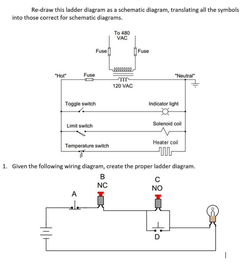
Electrical ladder diagrams are a graphical representation of the electrical connections and functions of a control circuit. These diagrams use ladder-like symbols to depict the components and connections within the circuit, making it easier to understand and troubleshoot electrical systems.
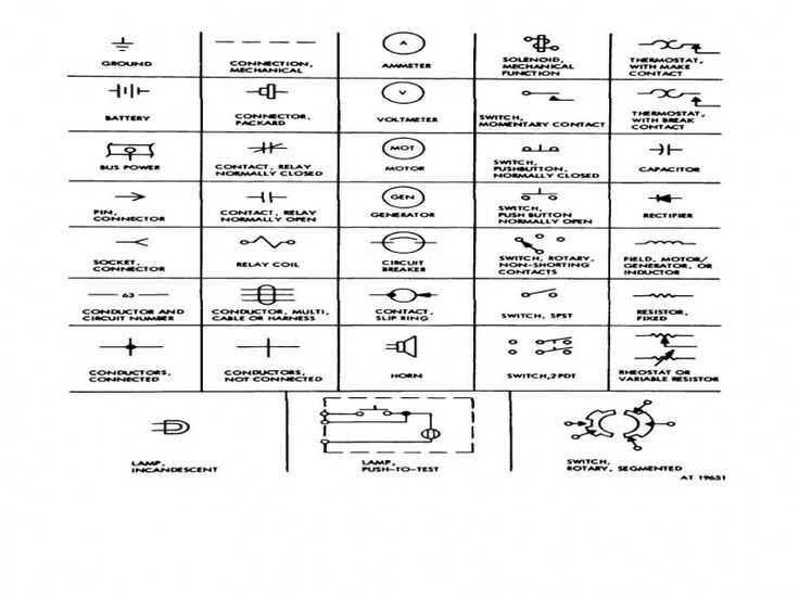
There are several commonly used symbols in ladder diagrams that represent various electrical components. For example, a coil symbol is used to represent a motor or a solenoid, while a contact symbol is used to represent a switch or a relay.
Other symbols include relays, timers, push buttons, limit switches, and pilot lights. Each symbol has a different meaning and function within the circuit, allowing engineers and technicians to easily interpret and analyze the system’s operation.
Understanding these symbols is crucial for anyone working with electrical circuits as it allows for efficient troubleshooting, repair, and maintenance of industrial equipment and machinery. With the help of ladder diagrams, technicians can quickly identify faulty components, locate wiring issues, and ensure the proper functioning of control circuits.
Electrical Ladder Diagram Symbols
Electrical ladder diagram symbols are graphical representations of electrical circuits commonly used in industrial settings. These symbols help engineers, electricians, and technicians understand and troubleshoot complex electrical systems.
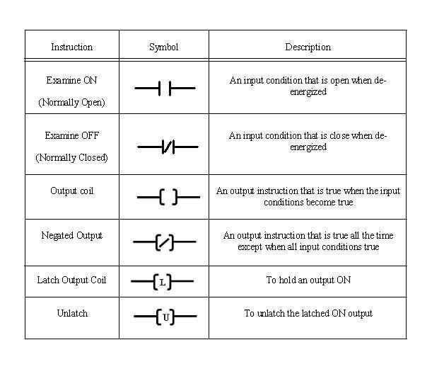
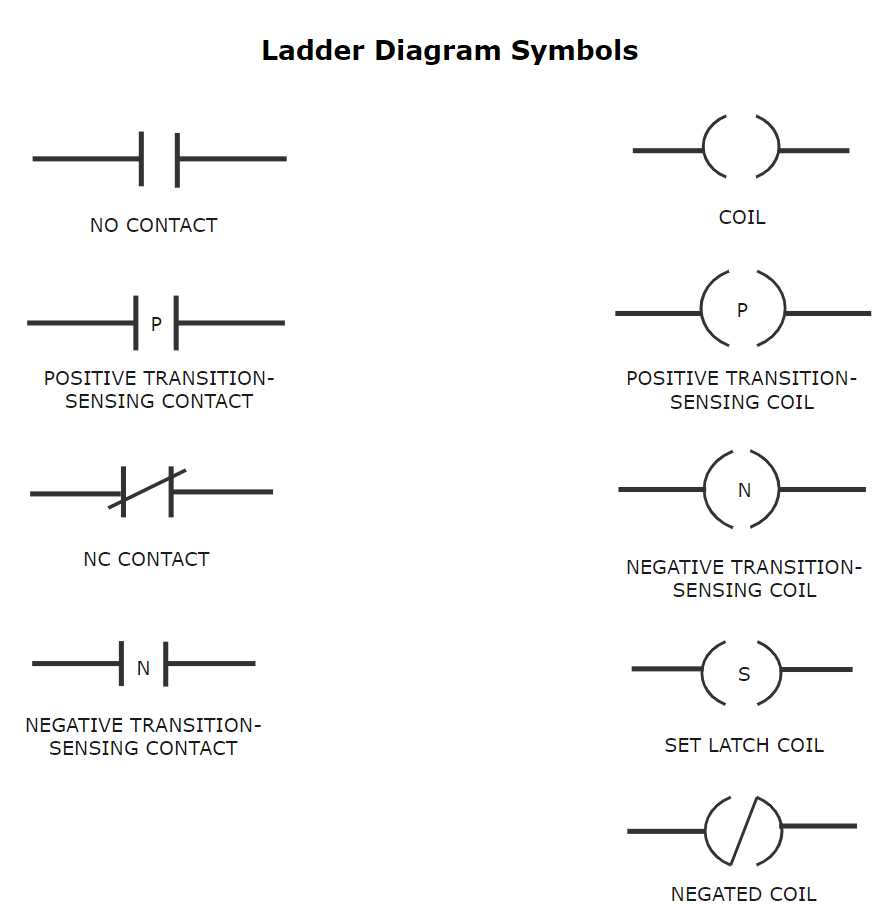
One of the most basic symbols used in ladder diagrams is the contact symbol. Contacts are used to represent the state of a switch or a relay. There are normally open (NO) contacts and normally closed (NC) contacts. An NO contact is represented by a line and a gap, while an NC contact is represented by a line with an X through it.
The coil symbol is another important symbol in ladder diagrams. It represents the coil of a relay or a solenoid valve. The coil symbol consists of a curved line with a diagonal line through it. When a current flows through the coil, the relay or solenoid valve is activated.
Other symbols commonly used in ladder diagrams include timers, counters, relays, transformers, and motors. These symbols help represent various electrical components and devices found in industrial applications.
In addition to the symbols, ladder diagrams also use lines to represent electrical connections. Horizontal lines represent wires, while vertical lines represent the power rails or busbars. The lines are connected through the use of rungs, which are horizontal lines that connect the various symbols.
Overall, electrical ladder diagram symbols play a crucial role in the design, analysis, and troubleshooting of electrical circuits in industrial settings. Familiarity with these symbols is essential for anyone working with electrical systems. They provide a standardized way to depict complex circuits, making it easier to understand and communicate about them.
Main Components of Electrical Ladder Diagrams
Electrical ladder diagrams are widely used in the field of electrical engineering to represent and visualize the electrical circuits and systems. These diagrams use specific symbols and connections to depict the various components and interactions within an electrical circuit.
1. Power Supply
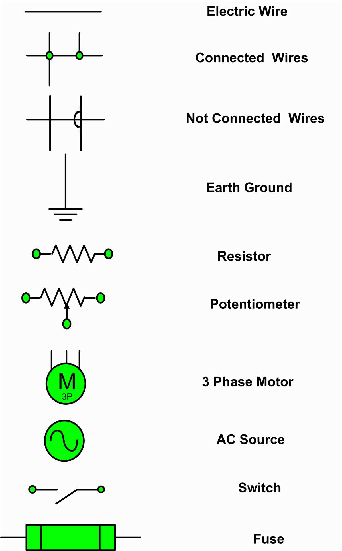
The power supply is the main source of electrical energy for the circuit. It is represented by a symbol that resembles a battery or an AC power source. The power supply provides the necessary voltage and current for the circuit to operate.
2. Contact Symbols
Contact symbols are used in ladder diagrams to represent the different types of switches and contacts in the circuit. These symbols include normally open (NO) and normally closed (NC) contacts, as well as push buttons, limit switches, and other types of switches. They indicate whether a connection is opened or closed in the circuit.
3. Coil Symbols
Coil symbols are used to represent various electrical coils and devices that produce magnetic fields. These coils can be electromagnets, solenoids, relays, or other similar components. The coil symbols are usually represented by a curved line with a transformer-like shape.
4. Interconnecting Lines
Interconnecting lines are used in ladder diagrams to connect the different components and illustrate the flow of current within the circuit. These lines are drawn horizontally or vertically and can cross or intersect each other to show the various connections and interactions between the components.
5. Control Relay Symbols
Control relay symbols are used in ladder diagrams to represent relays that control the operation of electrical circuits. These symbols usually have a rectangular shape with multiple contacts and coils. Control relays are used to switch the power supply on or off based on certain input signals or conditions.
6. Branches and Junctions
Branches and junctions are used in ladder diagrams to split or combine the flow of current within the circuit. Branches allow the current to flow in different directions, while junctions represent points where multiple connections meet. These components are represented by diagonal lines or dots in ladder diagrams.
In conclusion, electrical ladder diagrams consist of several main components, including the power supply, contact symbols, coil symbols, interconnecting lines, control relay symbols, and branches/junctions. These components work together to represent the various elements and interactions within an electrical circuit, allowing engineers and technicians to understand and analyze the circuit’s functionality.
Contacts
Contacts are one of the fundamental components in electrical ladder diagrams. They represent an electrical switch that can be either open or closed, depending on the state of the controlling device.
Contacts are typically represented by rectangular shapes, with the symbol of the controlling device placed inside the shape. The shape can be labeled as normally open (NO) or normally closed (NC), indicating the default state of the contact when no external force is applied.
The behavior of contacts in ladder diagrams is similar to that of physical switches. A normally open (NO) contact will allow the current to flow through when the controlling device is activated, while a normally closed (NC) contact will interrupt the current flow when the controlling device is activated.
Contacts are often used to control the operation of various electrical devices in a ladder diagram. They can be used to turn on or off motors, lights, valves, and other components, depending on the desired control logic.
In ladder diagrams, contacts can be connected in series or parallel to create complex control circuits. They can also be connected to coils, timers, and other control devices to create more advanced automation systems.
Coils
In electrical ladder diagrams, coils are represented by a circle or oval shape with a letter, number, or combination of both inside. Coils are used to represent devices that use electromagnetic fields to generate motion or to control electrical circuit functions. They are often found in relays, contactors, solenoids, and motor starters.
Coils are usually energized by a power source in the circuit and can produce a magnetic field when energized. This magnetic field is then used to activate or move other components within the electrical system. The letter or number inside the coil symbol represents the specific coil being used and helps identify its purpose in the circuit.
Example:
- A coil symbol with the letter “M” inside might represent a motor starter coil.
- A coil symbol with the number “1” inside might represent a solenoid coil.
- A coil symbol with the combination “CR” inside might represent a control relay coil.
Coils are an essential part of electrical ladder diagrams and play a crucial role in controlling and activating various electrical components. Understanding the symbols and their corresponding meanings can help in troubleshooting and designing electrical circuits.
Types of Electrical Ladder Diagram Symbols
Electrical ladder diagrams use various symbols to represent different components and functions in an electrical system. These symbols are essential for understanding and designing electrical circuits. Here are some common types of electrical ladder diagram symbols:
1. Contact Symbols:
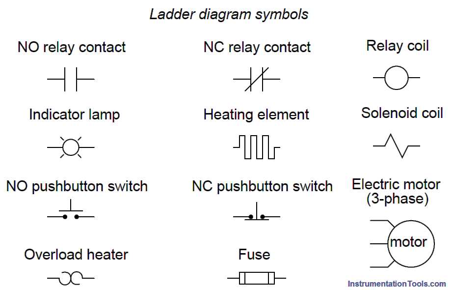
- Normally Open (NO) Contact: This symbol represents a switch or relay contact that is open in its normal or resting state. It allows current to flow through when activated.
- Normally Closed (NC) Contact: This symbol represents a switch or relay contact that is closed in its normal or resting state. It interrupts current flow when activated.
2. Coil Symbols:
- Relay Coil: This symbol represents a coil in a relay that generates a magnetic field when energized.
- Solenoid Coil: This symbol represents a coil in a solenoid that generates a magnetic field when energized.
3. Limit Switch Symbols:
- Normally Open (NO) Limit Switch: This symbol represents a mechanical switch that is normally open and closes when a specific condition is met.
- Normally Closed (NC) Limit Switch: This symbol represents a mechanical switch that is normally closed and opens when a specific condition is met.
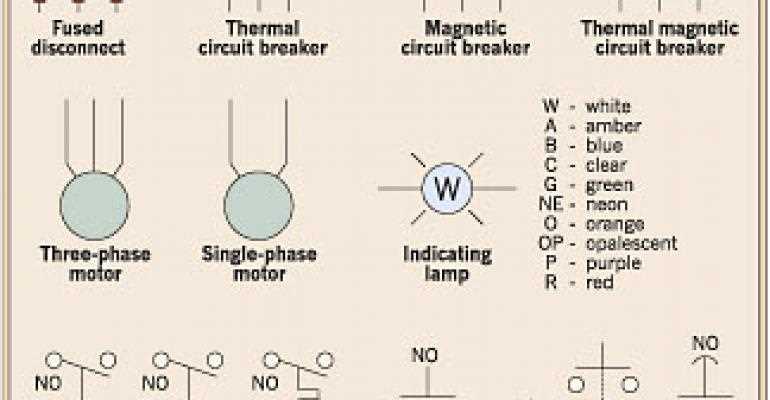
4. Motor Symbols:
- Motor: This symbol represents an electric motor, which converts electrical energy into mechanical energy.
- Motor Starter: This symbol represents a device used to start, stop, and protect an electric motor.
These are just a few examples of the many symbols used in electrical ladder diagrams. Each symbol has a unique meaning and helps convey specific information about the electrical circuit or system. Understanding these symbols is crucial for interpreting and designing electrical schematics.
Control Relays
Control relays are essential components in electrical ladder diagrams. They are used to control the flow of electricity in a circuit, allowing the activation or deactivation of various devices or components. Control relays are typically represented by specific symbols in ladder diagrams, making it easy to identify their function.
Normally Open (NO) Control Relay: A normally open control relay is represented by a rectangle with a diagonal line cutting through it. This type of relay is open when it is not energized and closes when a current flows through it. It is commonly used to control the activation of devices or components in a circuit.
Normally Closed (NC) Control Relay: A normally closed control relay is represented by a rectangular shape. This type of relay is closed when it is not energized and opens when a current flows through it. It is often used to control the deactivation of devices or components in a circuit.
Coil Symbol: The coil symbol represents the input or control signal for the control relay. It is represented by a circle with a letter or number inside it. The coil symbol is connected to the power source and determines whether the control relay is energized or not.
Contact Symbol: Contact symbols represent the output or controlled component of the control relay. There are several types of contact symbols, including normally open (NO), normally closed (NC), and make before break (MB). These symbols indicate the state of the contact when the control relay is energized or de-energized.
Interlocking Relay: An interlocking relay is a type of control relay that is used to prevent two devices or components from operating simultaneously. It is represented by a rectangle with a diagonal line and a small hook at the end. The interlocking relay ensures that only one device or component can be activated at a time, preventing potential issues or malfunctions.
Control relays play a crucial role in electrical ladder diagrams, allowing for the precise control and operation of various devices or components. Understanding the different symbols and their functions is important for designing and troubleshooting electrical circuits effectively.
Switches
The electrical ladder diagram is a graphical representation of an electrical circuit using ladder logic symbols. One of the most common symbols used in ladder diagrams is the switch symbol. Switches are devices that control the flow of electricity in a circuit. They can open or close a circuit, allowing or restricting the flow of electricity.
Types of switches:
- Normally open switch (NO): This type of switch is normally open, which means that it does not allow current to flow through the circuit when it is in its normal state. When the switch is activated or pressed, it closes the circuit and allows current to flow.
- Normally closed switch (NC): In contrast to the normally open switch, the normally closed switch is normally closed and allows current to flow through the circuit in its normal state. When the switch is activated or pressed, it opens the circuit and interrupts the flow of current.
- Selector switch: A selector switch is a type of switch that can be manually rotated to different positions, allowing the user to select different control options or functions. Each position of the selector switch corresponds to a different circuit or control sequence.
Switches are commonly used in electrical circuits to control the operation of various devices, such as lights, motors, and relays. They are essential components in ladder diagrams and play a crucial role in the overall functionality and control of an electrical circuit.
Sensors
In electrical ladder diagrams, sensors are represented by various symbols that indicate the type and functionality of the sensor. These symbols help in easily identifying and understanding the role of the sensor in the electrical circuit.
Some common sensor symbols used in electrical ladder diagrams include:
- Switches: Switches are used as sensors to detect the presence or absence of an object or condition. They can be represented by symbols such as push buttons, limit switches, proximity sensors, pressure switches, or flow switches.
- Sensors: Sensors are used to measure physical quantities such as temperature, pressure, level, or flow. They can be represented by symbols such as thermocouples, pressure transducers, level switches, or flow meters.
- Relays: Relays are electromechanical devices that act as sensors to detect or control electrical signals. They can be represented by symbols such as coil-operated relays, solid-state relays, or time delay relays.
- Motor starters: Motor starters are used as sensors to control the operation of motors. They can be represented by symbols such as motor contactors, overloads, or motor protective relays.
- Indicators: Indicators are used as sensors to provide visual or audible signals. They can be represented by symbols such as pilot lights, buzzers, or alarms.
In conclusion, sensors play a crucial role in electrical ladder diagrams as they detect and monitor various physical quantities and conditions. Understanding the symbols used to represent sensors is essential in order to read and interpret the diagrams accurately. By using these symbols, technicians and engineers can design, analyze, and troubleshoot electrical circuits more effectively.