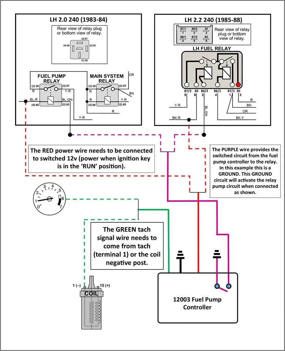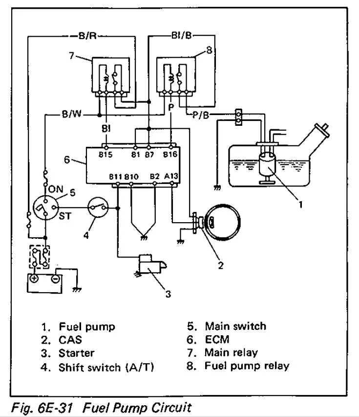
Properly mapping the connections for the power supply mechanism is crucial when troubleshooting or modifying the electrical systems of your vehicle. Ensuring each component receives the correct amount of power allows for reliable engine operation, especially during startup.
Check the control unit to determine how the components interact. Identifying the correct terminals that connect to the ignition system can prevent electrical faults. Trace the wires connected to the main switch and grounding to ensure proper current flow throughout the system.
Use a multimeter to check the continuity between terminals. Make sure the electrical contacts do not show signs of wear or corrosion. Replace any damaged connections immediately to avoid issues that may arise from interrupted power supply.
Labeling your connections during disassembly can save time. Whether you’re working with a new or older model, proper documentation of each wire’s function will speed up any repair work or modifications needed down the road.
Electrical Component Connection Overview
For reliable operation of the electrical components responsible for engine operation, proper wiring configuration is crucial. Ensure the correct wire gauge is used, as insufficient current flow can cause overheating or damage. Always check the component’s voltage and current ratings before installation.
Begin by identifying the control signal from the engine control unit (ECU). This will determine the timing of the activation and deactivation of the electrical system. Ensure the correct voltage is provided to the triggering mechanism, typically 12V DC for standard automotive systems.
Power Source: The main power supply should come directly from the battery. Use a fuse rated slightly higher than the expected current to protect the system from overcurrent. Place the fuse near the power source to minimize potential damage from short circuits.
Control Circuit: The control circuit will have a direct connection to the ECU, allowing the component to be turned on or off based on specific conditions, such as engine speed or ignition status. It’s important to use a relay with a proper current rating to handle the switching duties effectively.
Grounding: Proper grounding is essential for the safe and efficient operation of the system. Ensure the ground connection is solid and free from corrosion. A poor ground can cause erratic behavior or failure of the system to activate.
Confirm that the connecting wires are securely fastened, avoiding any loose connections which could result in intermittent operation. For added reliability, use heat-shrink tubing or electrical tape to insulate all exposed connections, preventing short circuits due to moisture or wear.
Before final installation, conduct a functional test to ensure the component operates correctly under all expected conditions. This test should include verifying the response times, voltage levels, and current flow during activation and deactivation sequences.
How to Identify Pinout in Circuit Schematic
Start by locating the component responsible for controlling electrical flow to the engine’s power system. This part will typically feature 4 or 5 pins. Identify each pin by its function: the input for power, ground, control signal, and output. The ground pin is usually marked with a “G” or “-”. The control pin connects to the engine control unit and is commonly labeled with “C” or “S”. The power input is often indicated with “B” or “P” and is connected to the battery or another power source. The output pin connects to the device that operates when the signal is activated, often labeled “O”.
Refer to the schematic for voltage and amperage specifications for each pin to confirm correct operation. Manufacturer documentation may provide additional confirmation of the pin configuration, as designs can vary.
Examine the color-coded connectors to ensure correct pin matching. Some schematics may show extra pins for diagnostic purposes, usually placed in separate sections. Use a multimeter to test the circuit and ensure the current is flowing through the correct pins.
Common Issues in Circuit and How to Fix Them

Start by checking the circuit for continuity. A broken wire or loose connection can lead to intermittent power supply. Use a multimeter to test for voltage across key points, ensuring the current flows properly when the system is activated.
Corroded terminals often cause poor connections. Clean the terminals with a wire brush and ensure a secure fit. If the corrosion is severe, replace the affected connectors to prevent further issues.
Another issue arises when the control module fails to send the proper signal. Inspect the module for fault codes and verify its output. If necessary, reset or replace the module to restore proper operation.
Faulty fuses or blown components are common causes of malfunction. Always replace fuses with ones of the same amperage. Check for signs of overheating or burning around any components in the circuit, as they could be causing failures.
Test the control switch, as it is responsible for initiating the power flow. If it’s malfunctioning, you might experience delayed or no activation. Replacing or cleaning the switch can often resolve this issue.
Lastly, ensure proper grounding. An inadequate ground connection can result in erratic behavior or complete failure. Inspect the ground wire for damage and ensure it is properly connected to the chassis.
Step-by-Step Guide to Testing Fuel System Relay Connections

To effectively diagnose issues with your vehicle’s power distribution system, follow these steps to test the relevant connections:
- Prepare Your Tools: Gather a multimeter, jumper wires, and safety gloves. Ensure the vehicle’s ignition is off before proceeding.
- Identify the Components: Locate the component responsible for activating the electric motor. This is usually housed in the relay box near the engine bay or fuse panel.
- Check Power Supply: With the ignition in the “on” position, use your multimeter to check for voltage at the input terminal of the relay. You should see the standard 12V.
- Test Activation Signal: Use the multimeter to measure the output at the activation terminal. If voltage is present, the system is being triggered correctly.
- Inspect Grounding: A faulty ground connection may prevent proper operation. Check the ground wire using your multimeter, ensuring continuity to the battery’s negative terminal.
- Test Load Side Circuit: Using jumper wires, simulate the operation of the system and check for voltage across the load terminals. If voltage drops or fluctuates, this could indicate a wiring issue.
- Verify Component Integrity: If all previous tests are successful, check the actual component itself. A resistance check on the motor or corresponding part can confirm if the issue lies there.
After completing these steps, you’ll be able to pinpoint the source of any malfunction and take the necessary action to repair or replace the faulty component.