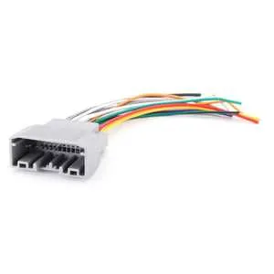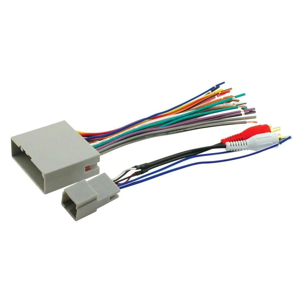
Ensure correct connections by referencing your car’s specific plug-and-play kit for the audio setup. For a smooth installation, follow the pinout configuration provided with the adapter. Identify the power, ground, and signal lines before starting the wiring process to avoid any malfunctions or electrical issues. These connectors are designed to make the replacement of factory radios or aftermarket systems straightforward, but proper orientation and secure connections are crucial.
First step: Inspect the wiring arrangement of the adapter and compare it with the vehicle’s factory wiring. This will help identify any mismatches that could cause improper operation. Make sure the voltage ratings align to prevent damage to your car’s electrical system.
Next: Match the speaker wires, taking into account the polarity (positive and negative). For accurate sound reproduction, connecting the speakers correctly is essential. Also, double-check the antenna and illumination wires if your new system requires them.
Lastly: Test all connections before finalizing the installation. Once everything is secure and checked, power up the system to confirm that the audio functions properly. If you encounter issues, verify each connection again, focusing on tightness and accuracy.
How to Connect Your Vehicle’s Audio System Properly
To ensure proper installation, follow the pinout scheme for the connection between your car’s stereo and the vehicle’s electrical system. Identify the matching wires for power, ground, speaker output, and accessory control. Always double-check the color codes provided by the manufacturer to avoid miswiring.
The power supply wire typically links directly to the battery. If your system includes an ignition-controlled power, connect the corresponding wire to the accessory line to prevent draining the battery when the vehicle is off. Make sure the ground wire is securely attached to a metal surface within the car.
Speaker connections should follow the standard color coding of the vehicle’s existing wiring. Match the left and right channels for both the front and rear audio system outputs. If you have a subwoofer, use the designated line for low-frequency signals to ensure clarity and deep sound reproduction.
For ease of troubleshooting, consider labeling each connection clearly as you work, especially for the antenna or additional system controls like the volume knob or steering wheel buttons.
Verify all connections once the system is set up. Turn on the vehicle and check each speaker’s output for sound clarity and balance. It is crucial to test for continuity in the connections to avoid electrical issues that could lead to poor system performance.
Understanding the Pinout Configuration of Scosche Wiring Harnesses

To ensure proper connection and functionality when integrating aftermarket electronics, understanding the pinout configuration of your adapter is crucial. Each terminal in the connector has a specific function, which must be followed carefully to avoid damage to both the vehicle’s electrical system and the new equipment.
- First Pin: Power Supply – This pin typically provides the 12V constant power needed to maintain the memory of the device, such as radio presets or clock settings. Ensure it’s connected to the correct 12V source.
- Second Pin: Ground – This pin should always be securely grounded. A weak or improperly connected ground can cause power fluctuations, leading to system malfunction.
- Third Pin: Ignition Power – This pin supplies power when the ignition is on. It powers devices like radios and amplifiers only when the vehicle is in use, saving battery life when the car is off.
- Fourth Pin: Speaker Connections – Each pin connected to this group is responsible for transmitting signals to individual speakers. Ensure each wire is linked to the corresponding speaker’s positive and negative terminals to avoid phase issues.
- Fifth Pin: Antenna Power – For systems with an automatic antenna, this pin sends power to raise or lower the antenna as needed. Incorrect connections can prevent the antenna from operating properly.
To avoid miswiring, it is essential to cross-reference the pinout with the specific component specifications. Pinout errors can lead to blown fuses, short circuits, or even permanent damage to the electronics. Always use a multimeter to check connections and ensure compatibility with the vehicle’s electrical system.
- Step 1: Verify the pin numbering of the connector before starting installation.
- Step 2: Confirm each wire corresponds to the correct input/output based on the pinout chart for the device you’re installing.
- Step 3: Double-check continuity of all connections before powering on the system.
By following these steps and using accurate reference materials, you can ensure smooth operation and extend the lifespan of both your car’s electronics and your new equipment.
How to Identify and Connect the Power and Ground Wires
To properly connect the power and ground cables, start by locating the red wire for power and the black wire for ground. These are standard color codes, and most wiring setups follow them. The red wire should be linked to a constant power source, typically a fuse box, while the black wire must be grounded to a metal part of the vehicle’s frame or the battery’s negative terminal.
Check the voltage output using a multimeter to ensure you’re connecting to the correct power source. The red cable should read 12V when the ignition is on, confirming it’s suitable for powering your device. For grounding, test the black wire against a known ground point. A consistent reading of 0V will verify a proper connection.
When securing the wires, strip about half an inch of insulation from both ends. Use a crimping tool or soldering to ensure a tight, secure connection. Avoid any loose wires that could lead to potential short circuits or intermittent power issues.
To minimize the risk of interference, avoid routing these wires near signal or speaker cables. Keep the power line as short and direct as possible to reduce voltage drop. If necessary, use a fuse holder on the power line to protect your system from surges or overloads.
Step-by-Step Guide to Customizing Your Wiring Setup for Aftermarket Installations
Start by identifying the correct pinout configuration for the vehicle and the aftermarket device. Use a multimeter to double-check that the voltage, ground, and speaker connections align with the new system’s requirements. Accurate identification is crucial to avoid potential damage to both the vehicle’s electronics and the new equipment.
Next, strip the wire insulation from the ends of each wire carefully. Ensure that each wire is long enough to make a secure connection with minimal strain. Use high-quality crimp connectors for a reliable and permanent connection. Soldering is an alternative if you prefer a more secure bond, but crimp connectors are generally easier and quicker.
Connect the ground wire to a clean, unpainted metal surface within the vehicle. Avoid using any shared ground points, as this could introduce noise into the audio system. If the installation involves powering an amplifier or other high-power devices, consider using a dedicated grounding point for optimal performance.
Ensure that the power wires are connected through a fuse holder rated for the appropriate amperage. This will protect both the vehicle’s electrical system and the new equipment from overcurrent situations. For additional safety, install an in-line fuse as close to the power source as possible.
After securing the main power and ground wires, connect the speaker wires according to the new unit’s specifications. Be careful not to mix positive and negative terminals, as this could result in distorted audio output or no sound at all. Label each wire clearly to avoid confusion during installation.
Once the wiring is complete, verify each connection using a continuity tester to ensure that no wires are shorted or disconnected. Then, carefully route the wires through existing channels or use cable ties to secure them, preventing movement and wear over time.
Finally, before powering up the system, check all connections once more and confirm that the new device is properly grounded. Once satisfied, test the system with the vehicle’s ignition turned on, ensuring all functions–power, audio output, and any additional features–are working correctly.