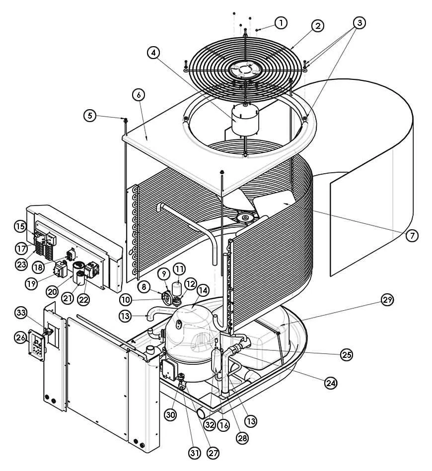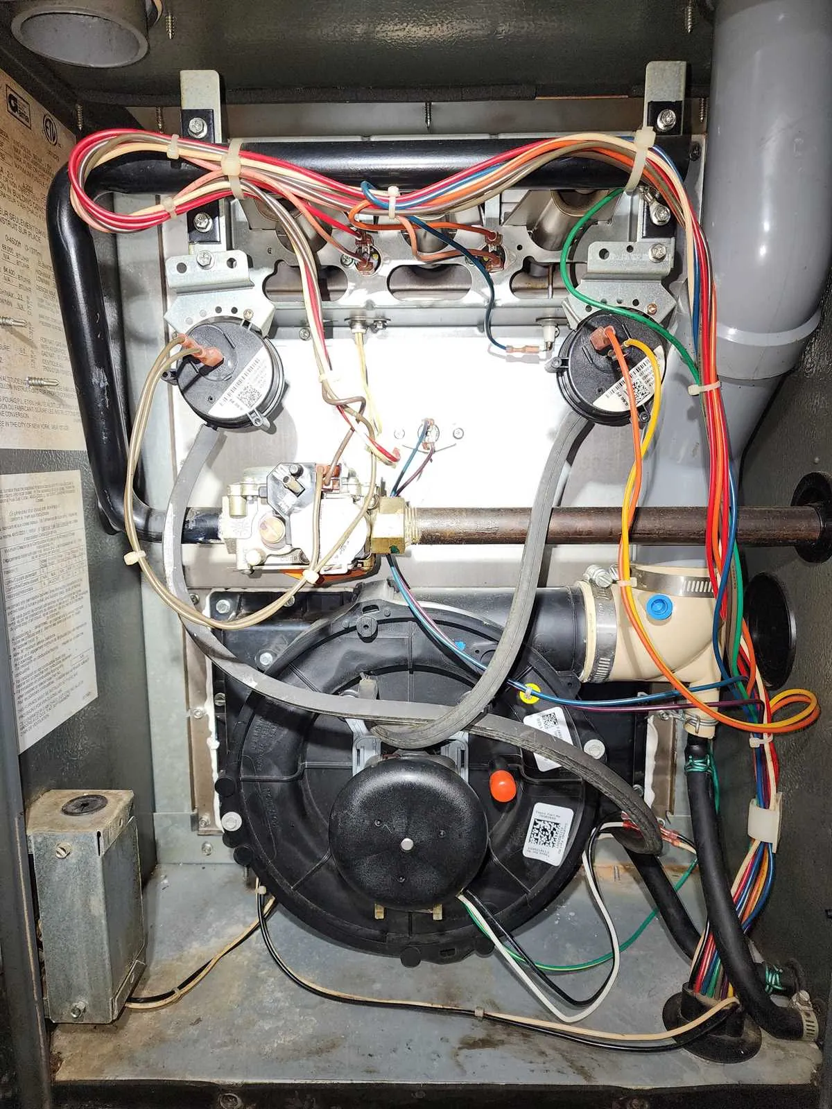
To ensure optimal operation and efficient maintenance of your heating unit, it’s crucial to identify and understand the role of each essential element within its structure. A visual guide to these components can streamline troubleshooting and repairs, enabling you to address issues promptly without unnecessary delays.
Start by familiarizing yourself with the blower motor and its associated wiring, which is responsible for air circulation. The control board governs the unit’s functions, and its correct calibration is vital for the overall system efficiency. Pay attention to the ignition system, which should ignite reliably and without delay.
Additionally, make sure to check the limit switch, designed to prevent overheating, and the gas valve to ensure proper fuel flow. Regular inspection of the heat exchanger is equally important, as any cracks can compromise the safety of your home. A detailed breakdown of each element helps simplify maintenance tasks and prevent unexpected breakdowns.
Key Components and Their Functions
For efficient heating, focus on the blower motor, which drives air circulation throughout the system. A malfunction here can lead to inadequate airflow. Ensure proper lubrication and check for any electrical issues, such as worn-out wires or faulty connections.
The ignition assembly plays a critical role in starting the heating process. If you notice delayed starts or intermittent operation, inspect the igniter and flame sensor. A cracked igniter can cause inconsistent heating, while a dirty flame sensor may prevent the burner from lighting.
Another vital element is the heat exchanger. It’s crucial for transferring heat from the combustion chamber to the air. Cracks or corrosion can lead to carbon monoxide leaks. Regular inspections are necessary to avoid these dangerous issues.
Do not overlook the thermostat. It acts as the system’s control center. If the heating cycles are irregular or the unit doesn’t turn on/off as expected, recalibrate or replace the thermostat. Incorrect settings can lead to inefficient energy use.
Lastly, the control board manages the communication between various components. Faulty connections or damaged relays on the board can lead to system failure. Always ensure the board is free of burnt-out spots or signs of moisture damage.
Identifying Key Components of Goodman Heating Systems
To ensure optimal performance of your heating unit, understanding its key elements is essential. Here’s a guide to help you locate and identify critical components that influence system efficiency and longevity.
- Heat Exchanger: A vital part for transferring heat. Its condition directly affects system performance. Inspect for cracks or corrosion.
- Inducer Motor: This motor drives the exhaust fan and helps vent gases. Check for smooth operation and absence of unusual noise.
- Blower Assembly: Responsible for circulating heated air. A malfunctioning blower can cause weak airflow. Ensure it’s clean and lubricated.
- Ignition Control: This component triggers the burner to start. Faulty ignition may prevent the system from firing. Test its functionality regularly.
- Flame Sensor: Detects the burner flame to ensure safe operation. Clean it periodically to avoid malfunction due to soot buildup.
- Gas Valve: Regulates fuel supply. It should be checked for leaks and proper function. A malfunction can disrupt heating efficiency.
- Transformer: Converts voltage for system control. A failure here could lead to power disruptions within the system.
- Limit Switch: Protects the system from overheating. Regular testing can prevent damage to critical parts.
By becoming familiar with these components and their roles, you can diagnose and address issues more efficiently, keeping your heating system running smoothly.
How to Troubleshoot and Replace Components

Start by disconnecting power and gas supply to ensure safety. Check the ignition system; a malfunctioning igniter can prevent startup. Inspect the flame sensor for dirt or wear, as it might cause the burner to shut down. If necessary, clean or replace it. Next, examine the blower motor and ensure the fan blades are not obstructed. If the motor is running but airflow is weak, verify the condition of the blower wheel and belts.
If the system doesn’t respond to thermostat commands, test the wiring for continuity. A faulty control board could be the cause if no power reaches key components. Measure the voltage across the terminals of the control board to confirm it’s operating correctly. If there’s no voltage, replacing the control board may be necessary.
For heating issues, check the heat exchanger for blockages or signs of damage. Use a flashlight to inspect the exchanger and verify proper air circulation. If you find cracks, it’s crucial to replace it to prevent carbon monoxide leaks. For air quality concerns, examine the air filter and replace it if it’s clogged or dirty.
If the system is producing strange noises, check for loose or worn-out fan blades, damaged belts, or debris in the blower assembly. Tighten or replace components as needed. Finally, ensure the condensate drain is clear of blockages, as this could cause moisture buildup and system shutdown.
Understanding Furnace Electrical Schematics for Maintenance
Verify wire connections before performing any repairs. Ensure all connections are secure to avoid electrical faults. A loose wire can cause intermittent issues or even complete system failure. Check for corrosion or wear on terminals and connectors.
Identify critical components such as the control board, ignition system, and blower motor. Make sure you understand how they interact through the electrical system. If troubleshooting, isolate each component to test for proper voltage and continuity.
Check circuit protection devices like fuses or breakers. A tripped breaker or blown fuse can prevent proper operation. Replace any faulty protection devices before proceeding with further diagnostics.
Follow color coding conventions to prevent wiring errors. Typically, wires are color-coded to indicate their function–black for power, white for neutral, and red or blue for control signals. Ensure that replacements match these conventions to avoid future confusion.
Use a multimeter to check voltage levels at key points in the circuit. Compare your readings with the manufacturer’s specifications for each component. If voltage levels are incorrect, there may be an issue with the transformer, control board, or a faulty connection.
Ensure proper grounding of the system. An inadequate ground can lead to electrical surges or instability. Check ground connections and make sure they are tightly secured and free of rust or damage.