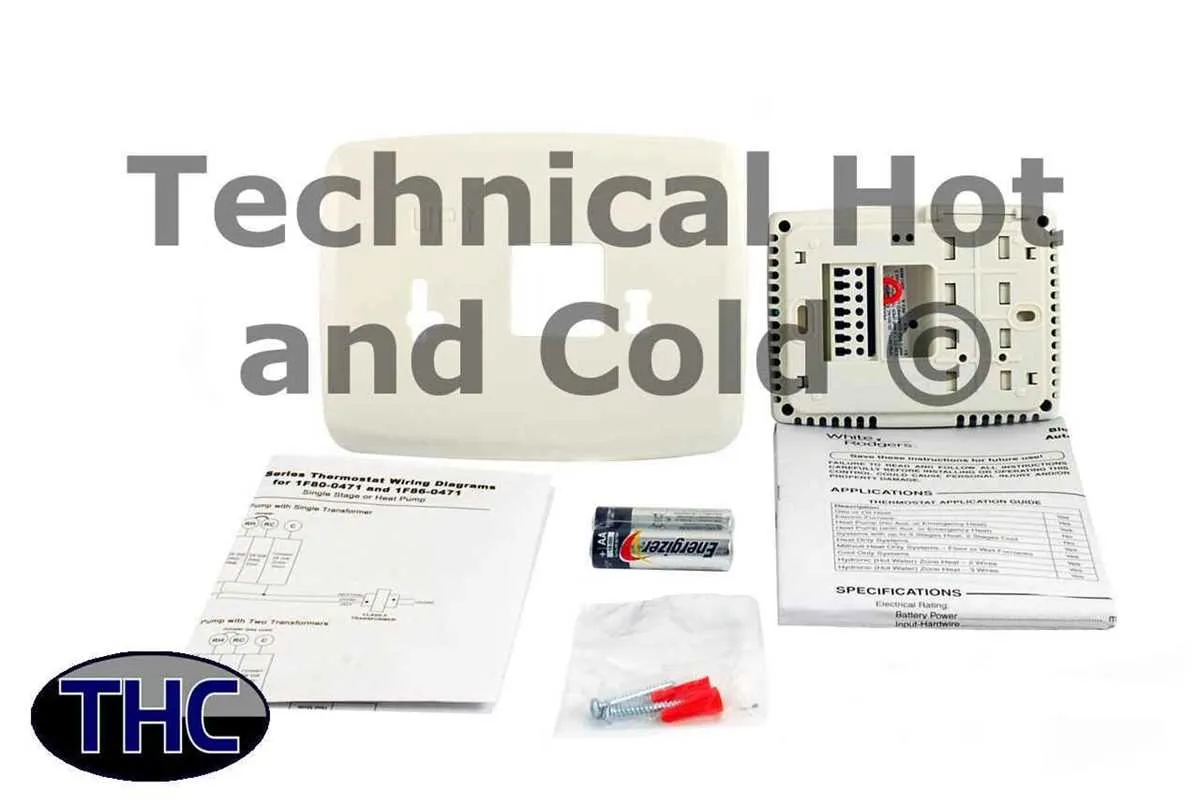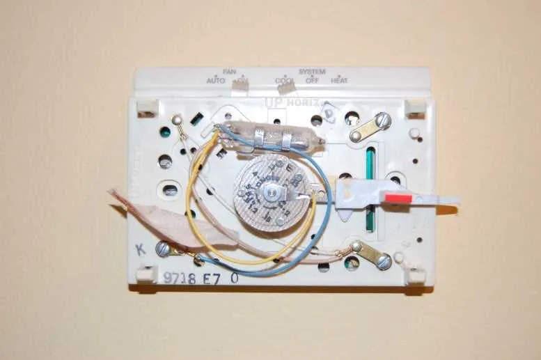
If you are installing or replacing a programmable heating and cooling control device, it is crucial to connect each wire correctly to ensure proper operation. The setup can seem complex, but by following a few specific guidelines, you can achieve a successful installation.
First, ensure the power to your HVAC system is completely turned off. This is critical to prevent any electrical hazards. Once the power is off, locate the terminals on the control panel where the wires will be attached. Typically, these include connectors for cooling (often marked “C”), heating (“W”), fan (“G”), and power (“R”). Make sure to match the wires with the corresponding terminals as described in the unit’s manual.
For most models, the R wire supplies power from the furnace or air handler, while the C wire serves as the common connection, ensuring continuous power flow for the system’s display and other features. The W wire is used for heating signals, and the G wire controls the fan.
If you’re switching from an older control model, it’s important to check for compatibility with the current wiring setup. Some older units might use different labels or wire colors, so verify that each connection is correct to avoid system malfunctions.
Thermostat Connection Guide
When setting up your climate control device, it’s essential to understand the correct connections for optimal functionality. Below is a clear explanation of common terminal assignments and their functions. Ensuring each wire is connected properly is key to avoid any malfunctioning of your system.
| Terminal | Wire Color | Function |
|---|---|---|
| R | Red | Power supply from the heating or cooling unit. |
| C | Blue | Common wire providing a return path for the current. |
| Y | Yellow | Cooling stage control. |
| W | White | Heating stage control. |
| G | Green | Fan control. |
| O/B | Orange or Blue | Reversing valve for heat pump systems. |
| Aux | Gray | Auxiliary heat for heat pump systems. |
Properly identifying each wire’s function before making connections is vital to avoid issues like incorrect heating or cooling cycles. If unsure about the system or wiring colors, always refer to the unit’s manual for guidance or consult an expert to ensure safe installation. Always disconnect power before making any changes.
Understanding the Basic Wire Connections for Climate Control Systems

When installing or replacing a climate control unit, proper identification of wire connections is crucial for efficient operation. Here are the most common terminals you’ll encounter:
R (Red): This terminal is for the power supply, providing voltage to the system. Always connect the R wire to ensure the unit receives electricity.
C (Common): The C wire completes the circuit for the 24V power, allowing the system to operate continuously. This is essential for digital units.
Y (Cooling): The Y wire controls the cooling system. It activates the air conditioner when the set temperature exceeds the target.
W (Heating): The W wire controls the heating function. It triggers the furnace when the temperature falls below the desired level.
G (Fan): This wire connects to the fan control. When connected, it allows the fan to run independently of the heating or cooling systems.
O/B (Reversing Valve): These terminals are for systems with heat pumps. The O wire is used in cooling mode, and the B wire is used in heating mode to switch the reversing valve.
Ensure that each connection is made securely to avoid malfunctions. Double-check for any short circuits or improper wiring before powering on the unit.
Step-by-Step Guide to Connecting Your HVAC Control Unit
Ensure the power to your HVAC system is completely turned off before starting the installation. This will prevent any electrical accidents during the process.
Identify the terminals on the control unit that correspond to the wiring setup of your heating and cooling system. Typically, you’ll find the following connections: R (power), C (common), W (heating), Y (cooling), and G (fan). Refer to the control unit’s manual for precise terminal markings.
Begin by connecting the R terminal to the power wire. This is typically a red wire, which supplies the 24V power to the system. If you have a C wire, it should be connected to the C terminal to provide a return path for the power, completing the circuit.
Next, link the W terminal to the wire that controls the heating element. This wire will likely be white. Similarly, connect the Y terminal to the wire responsible for activating the cooling system, often a yellow wire.
For the fan operation, the wire connected to the G terminal (usually green) should be attached. This wire controls the blower motor for circulating air throughout the system.
Once all wires are connected to their respective terminals, double-check for any loose connections. Tighten all screws securely to prevent issues once the system is powered on.
After the connections are complete, carefully mount the unit onto the wall. Ensure that the placement does not obstruct airflow or interfere with other system components.
Power up your HVAC system and test the system functions to ensure that each component (heating, cooling, and fan) responds as expected. If the system does not function properly, verify that all wires are correctly connected and the terminals are secure.
Troubleshooting Common Wiring Issues in HVAC Control Systems
When faced with heating or cooling malfunctions, it’s essential to inspect the connections closely. Incorrect installation or loose connections often cause system failures.
- Check the power supply: Ensure that the system is receiving power. A simple voltage tester can verify if the unit is correctly connected to the main electrical panel.
- Verify terminal connections: Examine each terminal for secure connections. If a wire is loose or disconnected, it could cause erratic behavior or prevent the system from functioning.
- Inspect for corrosion: Corrosion or rust on terminals can lead to poor conductivity. Clean any affected terminals with a wire brush and re-secure them to ensure proper function.
- Identify mismatched wire colors: Confirm that the wire colors match the system’s specifications. A mismatch could lead to improper control responses.
- Examine the jumper wire: Some models require a jumper wire between certain terminals. If the jumper is missing or improperly placed, the system may not operate as expected.
If no issues are found with the connections, test the unit by manually adjusting settings. This can help determine whether the problem lies with the control unit itself or the external components.