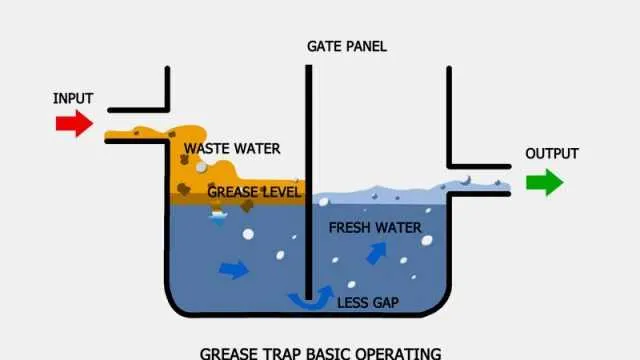
Proper arrangement of waste oil interceptors is crucial for preventing grease buildup in kitchen drainage lines. Ensuring that inflow and outflow pipes are correctly positioned allows for efficient separation of fats and oils from wastewater, minimizing clogging risks and maintaining smooth flow.
Placement of baffles and access points must follow recommended specifications to facilitate regular cleaning and inspection. Incorrect alignment or sizing can lead to premature blockages or malfunction, resulting in costly repairs and environmental concerns.
Integrating venting components appropriately helps maintain atmospheric pressure, which is essential for the interceptor’s optimal operation. Using standardized piping measurements and slope gradients guarantees that liquids pass through at the intended rate, enhancing overall system performance.
Optimal Placement of Waste Interceptors in Commercial Kitchen Designs

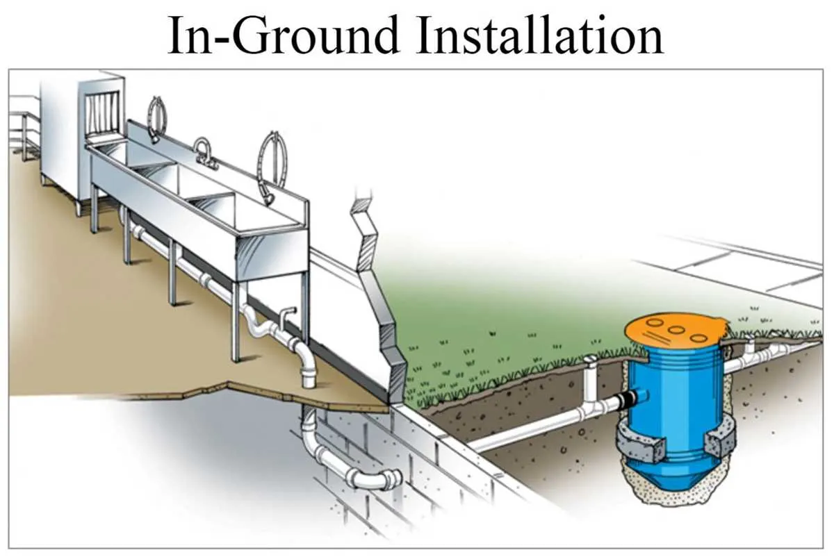
Position the interceptor unit as close as possible to the primary source of oily effluents to minimize the length of piping and reduce the risk of blockages. Typically, installation is recommended near sinks, dishwashers, or food prep stations where fat-laden wastewater is generated.
Ensure the device is accessible for routine maintenance and cleaning–locating it in a well-ventilated area with sufficient clearance around it facilitates removal of accumulated residues and inspection. Avoid placing it in confined or hard-to-reach corners.
When integrating the device within the layout, consider the flow direction of wastewater to maintain proper gravity drainage. The unit should be installed upstream of the sewer connection but downstream of kitchen equipment to intercept solids and fatty substances before entering the main drain system.
Compliance with local building codes often dictates minimum setback distances from walls, electrical panels, or heat sources; confirm these requirements during planning to prevent costly adjustments.
Pipe configuration from sinks to grease interceptor
Ensure all drain lines from kitchen sinks connect directly to the interceptor inlet without intermediate junctions to prevent blockages. Use 4-inch diameter pipes for main runs to maintain adequate flow velocity and avoid sediment buildup. Employ smooth-walled PVC or ABS piping to reduce resistance and facilitate cleaning.
Install a vent pipe near the interceptor to equalize pressure and prevent siphoning of the interceptor’s contents. Position the piping with a consistent slope of 1/4 inch per foot towards the interceptor to ensure efficient drainage. Avoid sharp bends by using 45-degree fittings instead of 90-degree elbows to minimize flow turbulence.
Separate fixtures such as dishwashers or pot sinks should have individual branch lines converging into a common header before entering the interceptor. This header pipe must also comply with size and slope requirements to prevent backups. Incorporate cleanout access points upstream and downstream of the interceptor for routine maintenance and inspection.
Cleanout Access and Maintenance Points
Ensure cleanout openings are installed at all critical junctions to allow effortless debris removal and inspection. These access points should be located upstream and downstream of the grease interception unit for efficient clearing of buildup and blockages.
Maintenance hatches must be easily reachable without dismantling major components. Position them near inlet and outlet lines to facilitate routine flushing and manual cleaning. Properly sealed covers prevent odors and leaks while providing quick access.
Include access ports at bends and pipe junctions where solids are prone to accumulate, allowing targeted intervention without system disassembly. Use threaded or gasketed plugs for repeated openings and secure resealing.
Regularly scheduled maintenance should focus on these points to prevent clogging and preserve flow efficiency. Clearly label access locations on layout plans for swift identification during service calls.
Incorporate vent pipes adjacent to cleanouts to balance pressure and reduce the risk of suction or backflow during cleaning operations. This also improves safety and prolongs system lifespan.