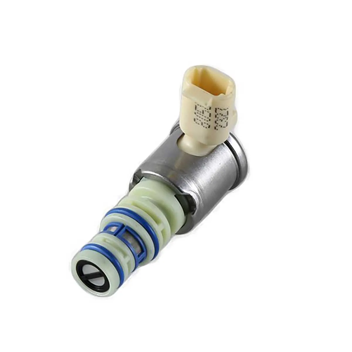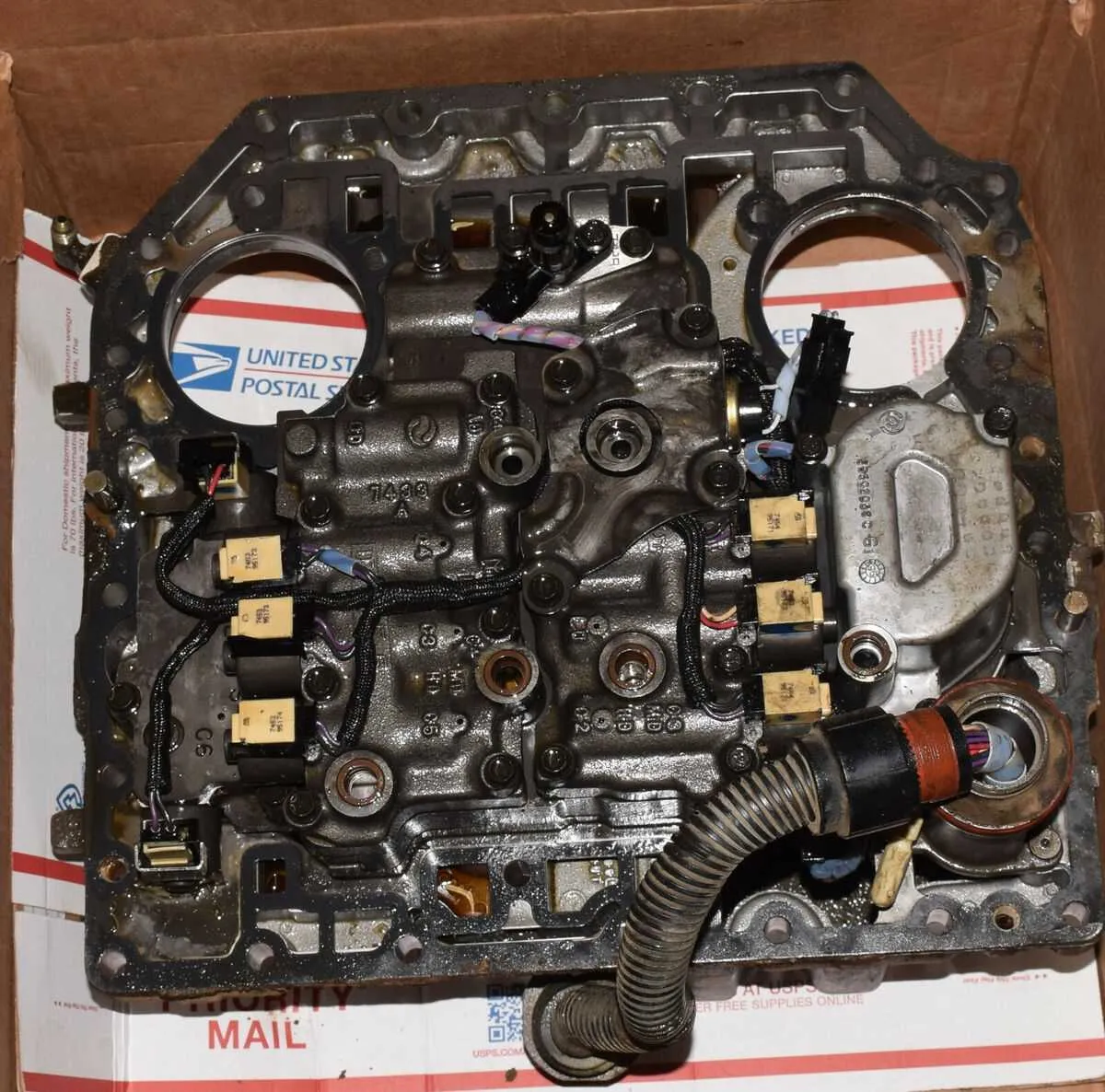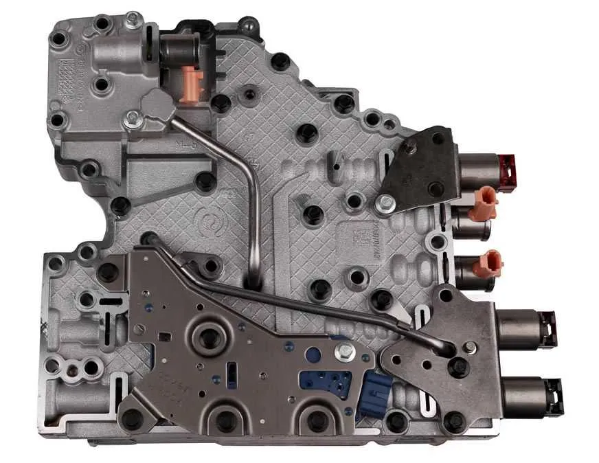
When troubleshooting transmission shifting issues, start by examining the components responsible for gear engagement. These small yet crucial elements play a vital role in ensuring smooth operation of the transmission system. If your vehicle exhibits irregular shifting behavior, it’s likely due to malfunctions within these parts, which can be identified through their electrical and mechanical interactions.
Examine the electrical connections closely, as poor contacts can lead to inconsistent or failed activation. Check for any corrosion or damage around the wires and connectors. Proper functioning of the shift mechanism relies heavily on uninterrupted electrical signals to engage specific gears when needed. In addition, verify that the internal parts responsible for regulating pressure and valve movement are not obstructed or worn out.
For accurate diagnostics, rely on a detailed reference to pinpoint the specific malfunction. Understanding the function of each component in the system will allow you to take precise action, whether it’s replacing or cleaning certain parts. In many cases, small errors in wiring or faulty components are all it takes to resolve transmission problems and restore proper vehicle performance.
Understanding Transmission Control Valve Components

For efficient transmission operation, it’s crucial to identify and understand the role of each valve component in the system. These components control fluid flow to specific parts, enabling gear changes and other essential functions. Below is a breakdown of key elements that ensure smooth transmission operation.
- Component 1: Valve Body Actuator – This element controls the hydraulic fluid flow, crucial for shifting gears. Regular inspection ensures it responds quickly and efficiently to command signals.
- Component 2: Pressure Regulator – This unit maintains optimal hydraulic pressure. If it malfunctions, shifting can become erratic, leading to performance issues.
- Component 3: Control Valve – Responsible for regulating the direction of fluid to engage different transmission modes. A malfunction can cause slipping or hard shifting.
- Component 4: Electrical Actuators – These are responsible for responding to electrical signals that adjust the hydraulic pressures. A failure in these parts often results in complete loss of shifting functionality.
Each of these parts must be regularly checked for wear and proper function. Early detection of issues, such as fluid leaks or electrical failures, can prevent more serious transmission problems later on. To properly maintain these components, use high-quality fluid and always follow the manufacturer’s maintenance schedule.
Common Symptoms of Component Failure:
- Delayed shifting or no shifting at all
- Erratic gear changes
- Unusual noises from the transmission
- Loss of power or slipping
In case of any failure, it is critical to perform a diagnostic check to pinpoint the specific faulty component. Replacing damaged parts promptly will maintain transmission performance and avoid costly repairs down the line.
Understanding the Function of Each Valve Actuator in the Transmission

Each valve actuator plays a critical role in managing gear selection and transmission fluid flow. There are multiple actuators, each designed to control a specific shift sequence, ensuring smooth transitions between gears. The primary function of these devices is to control the hydraulic pressure applied to different parts of the transmission, enabling precise gear engagement or disengagement.
The first actuator handles the application of pressure to the low and reverse clutches, facilitating shifts into these gears when necessary. This actuator also manages pressure in relation to torque converter clutch control, ensuring optimal engagement when required. The second actuator, which controls the high-range clutches, is essential for smooth shifts into the higher gears, including overdrive, by modulating the hydraulic pressure at the right moments to avoid rough shifting.
The third actuator is involved in coordinating the intermediate gears, optimizing the transition between each range. These actuators must respond to input from the vehicle’s control system, taking into account vehicle speed, engine load, and throttle position. Proper calibration and maintenance are crucial for these components to perform accurately, as even slight malfunctions can lead to harsh shifts or slipping between gears.
To ensure smooth operation, all actuators are electronically controlled, responding to signals from the transmission control module. These devices use solenoids to regulate fluid flow and pressure, meaning that each shift depends on an electrical signal that prompts the solenoid to open or close, influencing hydraulic pressure within the transmission.
When performing diagnostics or maintenance, always check for electrical issues such as faulty wiring or solenoid malfunction. Miscommunication between the control module and the actuators can cause delayed or erratic shifts. Periodic testing and inspection are recommended to ensure the actuators are working within factory specifications, as improper operation can lead to transmission wear and damage.
Troubleshooting and Testing Transmission Control Components with Wiring Schematics
To efficiently identify issues with the transmission control elements, start by reviewing the wiring schematic. This provides a clear view of electrical connections and circuit pathways, which is crucial for pinpointing faults. Begin by checking for proper voltage at the component’s terminals when the ignition is on, ensuring the wiring is intact and there are no visible signs of damage or corrosion.
Next, use a multimeter to measure resistance across the terminals. Compare the results with manufacturer specifications–resistance outside the specified range often indicates internal malfunction or wiring issues. Continuity testing can confirm whether the circuit is open or shorted.
If voltage and resistance readings appear normal but the component is not responding, inspect the signal input from the transmission control module. An oscilloscope can be used to monitor the signal waveform, which should match expected patterns during operation. Abnormal signal characteristics can point to issues within the control unit or the transmission wiring harness.
In case of erratic shifting behavior or failure to engage gears, verify ground connections. Poor grounding can result in erratic operation, so ensure the ground path is clean, secure, and free of oxidation. Additionally, check for any stored diagnostic trouble codes (DTCs) that may indicate specific malfunctions within the system.
After confirming all electrical checks, perform a functional test by manually activating the component in question using a scan tool or direct application of power, ensuring it responds appropriately to control signals. If the component does not activate, replacement or further inspection of associated parts may be necessary.
Common Issues with Transmission Valve Actuators and Their Solutions
Inconsistent gear engagement: One of the most common issues is erratic gear shifts or slipping. This is often due to a malfunctioning valve actuator or poor electrical connections. Check for corrosion or dirt around the electrical connectors. Clean the terminals and ensure all connections are tight. If the problem persists, inspect the wiring for shorts or breaks, and consider replacing the actuator unit.
Delayed or harsh shifting: If your vehicle experiences delays in shifting or hard shifts, the problem could be with the pressure control system. Test the pressure sensor and control valve for wear or damage. Replace any components that are not functioning correctly. Also, ensure the transmission fluid is at the correct level and not contaminated.
Erroneous fault codes: Transmission-related error codes might point to a malfunctioning actuator or valve assembly. Use a diagnostic scanner to read the codes and identify the specific issue. Fault codes such as P0776 or P0780 may indicate issues with valve function. Clearing codes temporarily can mask the problem, so perform a thorough inspection and replace any faulty actuators.
Loss of power or poor acceleration: A malfunction in the actuator system can lead to power loss or a failure to shift properly under load. This is often due to improper actuator operation, causing fluid pressure imbalance. Test the actuator’s response and check the fluid pressure values. If abnormal readings occur, replace the malfunctioning component to restore normal operation.
Fluid leakage: Leaks from the actuator or associated seals can cause a drop in hydraulic pressure, leading to transmission problems. Inspect the actuator housing for cracks or damage. Replace seals or gaskets as needed to prevent leaks and restore system performance.