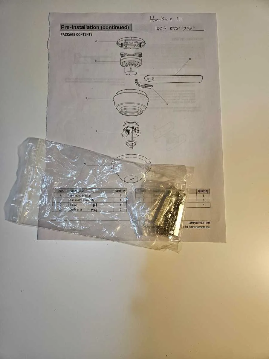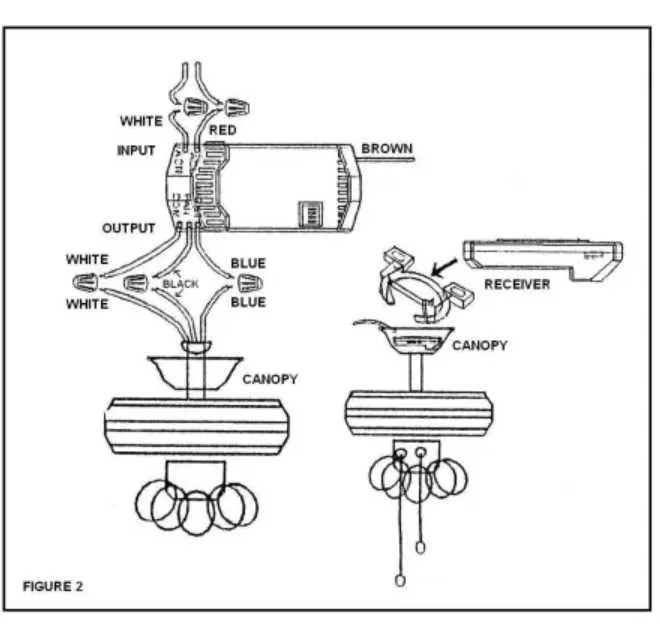
To effectively identify and replace individual elements of your indoor rotary blower, start by consulting a detailed schematic that maps each mechanical and electrical component. Precise recognition of blades, motor housing, mounting brackets, and control switches ensures accurate maintenance and prolongs operational life.
Focus on the motor assembly and blade attachment points: these are critical for smooth rotation and balanced airflow. Any signs of wear or imbalance often originate here and can cause noise or inefficiency. Replacement of these specific subunits, rather than the entire device, is a cost-efficient approach.
Wiring harnesses and capacitor locations are often overlooked but vital for performance. Understanding their placement within the framework allows for safer troubleshooting and prevents damage to electronic circuits during repairs. Accurate part identification minimizes downtime and guarantees proper function after servicing.
Detailed Schematic for Home Air Circulator Components
To ensure accurate identification of each component in your residential air movement device, refer directly to the labeled illustration provided by the manufacturer. Key elements include the motor assembly, blade arms, mounting bracket, capacitor, and switch housing. Each item is precisely numbered for straightforward ordering and replacement.
The motor housing contains the rotor and stator, critical for rotation. Blade supports attach firmly via screws to the motor shaft, enabling balanced airflow. The capacitor regulates electrical charge, impacting speed control and efficiency. Switch components are integrated within the canopy for seamless operation.
When inspecting the unit, confirm the integrity of the wiring harness connecting the motor to the power source, ensuring no frayed or exposed wires. The pull chains or remote receiver module must align with the schematic for compatibility. Proper assembly depends on following the reference layout to maintain safety standards and performance.
For replacements, cross-check part numbers against the diagram’s legend to avoid mismatches. Use the exploded view to visualize assembly order, which aids in troubleshooting mechanical or electrical faults. This schematic is essential for both routine maintenance and comprehensive repairs of household airflow equipment.
How to Identify Key Components in Hampton Bay Ceiling Fan Diagrams
Start by locating the motor assembly, which is typically central and depicted with winding coils or a cylindrical shape. This unit drives the entire mechanism and is essential for operation.
Blade arms attach directly to the motor housing; identify these by their elongated, flat structure extending outward. They often connect via screws or clips shown in exploded views.
The light kit assembly, if included, is usually illustrated beneath the main motor unit and may show bulbs, glass shades, and wiring connectors. Look for electrical components grouped together in this section.
Switch housing or control modules appear as small boxes or plates near the mounting bracket; these parts regulate speed and lighting functions.
Mounting hardware such as brackets, screws, and canopy covers are generally outlined at the top of the schematic and provide the structural support needed for secure installation.
Pay attention to wiring diagrams often included alongside the mechanical layout. Color-coded lines and labels indicate connections between the power source, motor, light, and controls, clarifying the electrical flow.
Identifying these elements precisely allows for efficient troubleshooting, ordering replacements, or conducting repairs without guesswork.
Troubleshooting Common Issues Using Model Component Schematics
Start by locating the exact assembly in the schematic to identify faulty elements quickly. For electrical malfunctions, focus on the wiring layout and motor connections to detect loose or damaged wires.
- Blade wobbling: Check the mounting bracket and blade arms for wear or misalignment as indicated in the illustration. Tighten all screws and replace bent components.
- Light not turning on: Verify bulb socket wiring and switch assembly in the wiring map. Replace blown fuses or burnt-out bulbs accordingly.
- Remote control issues: Inspect the receiver unit and antenna connection depicted in the circuitry. Ensure batteries are fresh and connectors are intact.
- Unusual noise during operation: Examine motor housing, blade arms, and balancing kit positions. Lubricate moving parts and replace damaged dampers as outlined.
Use the detailed schematic reference to cross-check component codes before ordering replacements, ensuring compatibility and reducing downtime.
- Identify the problem area visually on the exploded view.
- Trace electrical paths if applicable, using the wiring chart.
- Confirm mechanical part integrity against the component legend.
- Order or replace parts only after verifying model numbers on the layout.
Following these steps expedites repairs by targeting exact assemblies and eliminates guesswork in part selection and installation.
Step-by-Step Guide to Ordering Replacement Components from Schematics

Identify the exact model number and revision code of your fixture before referencing any schematic. This ensures compatibility and prevents ordering incorrect pieces.
Locate the exploded view or assembly illustration for your specific unit, focusing on the detailed callouts and reference numbers adjacent to each element.
Match the numeric or alphanumeric identifier from the schematic to the official parts list provided by the manufacturer or authorized distributors.
Cross-check the description, dimensions, and material specifications listed to confirm it corresponds precisely with the worn or damaged item.
Use the official supplier’s catalog or website input fields to enter the part number exactly as indicated, avoiding generic terms to reduce errors.
Verify availability and note any alternatives or updated versions suggested by the supplier, especially if original components are discontinued.
Include any additional hardware or connectors shown in the diagram, as these are often sold separately and critical for proper installation.
Double-check shipping details and warranty terms associated with the order to ensure proper delivery and post-purchase support.
Keep a digital or printed copy of the schematic and order confirmation for reference during installation or future maintenance.