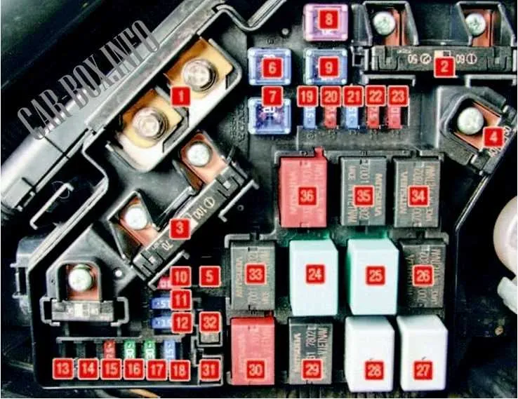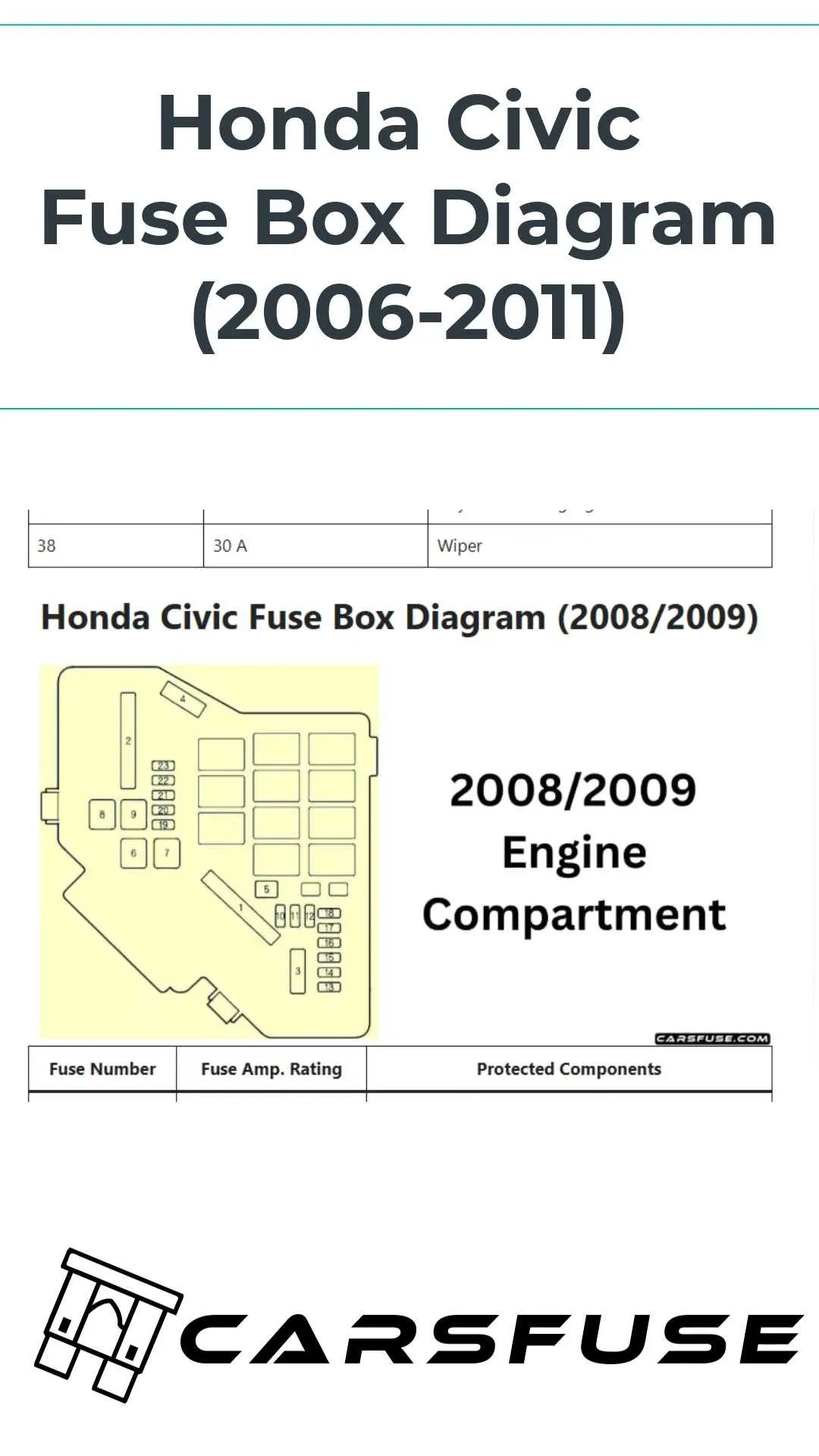
For accurate troubleshooting and efficient maintenance of your vehicle’s electrical system, knowing the layout of key components is crucial. This guide focuses on understanding the specific configuration of switches, fuses, and control units that manage the power distribution across various parts of the car.
When diagnosing issues related to the ignition, lights, or other essential functions, pinpointing the exact location of the components that manage these tasks is vital. Each unit in the vehicle’s electrical setup has a designated position, and recognizing their connections will help streamline repairs.
Detailed knowledge of component placement can prevent unnecessary disassembly, saving both time and money. Ensure you have access to the correct placement information to handle any electrical interruptions swiftly. The schematic layout provides essential reference points, allowing you to identify potential causes of malfunction without error.
For better accuracy, use a reliable source when cross-referencing the system’s component map. Knowing where each item is located will guide you effectively through any electrical repair or diagnostic task. The configuration will also help in identifying which elements are prone to wear and tear over time.
Following a well-structured schematic ensures that all connections are inspected and properly handled, avoiding costly mistakes during maintenance or troubleshooting sessions. Keep this reference handy whenever working on electrical systems in your vehicle.
Detailed Breakdown of Electrical Component Circuits

For precise troubleshooting, locate the fuse box and understand the layout of the electrical switches in the engine compartment and cabin. The main components for managing power distribution are typically housed in two primary boxes: the under-hood unit and the interior fuse panel.
The first unit houses vital circuits, including engine management, lighting, and ignition controls. Check the under-hood box for connections related to components like fuel systems and air conditioning. The second panel inside the cabin governs functions such as window motors, interior lights, and keyless entry. Each switch should be tested for continuity to ensure proper function.
Ensure that the connections are clean and free of corrosion, which can lead to irregular performance. Often, the primary issue lies in a faulty contact within the specific component’s circuit, which can be traced by using a multimeter to test for voltage inconsistencies across connections.
Identify the primary terminals for each power supply and cross-reference with the component layout provided in your vehicle’s manual for quick troubleshooting. This method guarantees efficient and targeted diagnostics.
Make sure to use fuses and switches with matching amperage ratings to avoid further electrical complications. Regular inspection of these connections is crucial to maintaining the reliability of all power functions within the vehicle.
How to Locate the Relay Panel
To find the electrical control unit on this model, first, open the driver’s side door. The panel is typically located beneath the dashboard, near the left side of the footwell. You may need to remove the cover, which is usually secured with clips or screws.
If the panel isn’t visible, check the area near the steering column. It may be hidden behind a plastic trim piece. Once you have access to the area, carefully pull off the cover to reveal the panel. It should be in plain view, with each individual component clearly marked for identification.
In some cases, the control box might be located under the hood. Look near the battery or fuse box for a secondary panel, often secured with a latch. If you’re having trouble, consult the vehicle’s manual for specific instructions regarding component locations.
Important: Always turn off the ignition before attempting to access any electrical parts. If you have trouble identifying the correct component, consult a professional to avoid potential damage to the vehicle’s electrical system.
Identifying the Function of Each Relay in the 2008 Honda Civic
The fuse box located in the engine compartment houses several relays, each serving a distinct purpose to ensure the vehicle operates smoothly. These electrical switches control essential functions like the fuel pump, air conditioning, headlights, and more.
1. The first relay controls the fuel pump circuit. This relay ensures fuel is supplied to the engine when the ignition is on. A malfunction here can lead to engine startup issues or stalling.
2. The second is responsible for the cooling fan. It activates the radiator fan to prevent the engine from overheating. A failure in this relay could cause the engine to reach dangerously high temperatures.
3. Another relay is linked to the horn. This relay is activated when the horn button is pressed, delivering power to the horn. If the horn is unresponsive, the relay could be the culprit.
4. The next relay controls the air conditioning compressor. If your A/C fails to cool or operate properly, this relay is a common point of failure.
5. There’s also a relay dedicated to the headlights. It ensures proper functionality of both low and high beam settings. A problem with this relay may result in one or both beams not working correctly.
6. Lastly, the ignition system relay works by sending power to the ignition coil and spark plugs. A faulty ignition relay can prevent the engine from starting or cause intermittent starting issues.
To troubleshoot these relays, it is important to check the continuity with a multimeter or replace them with known working units to identify any issues affecting vehicle operation.
Steps for Diagnosing Electrical Switch Issues in a 2008 Vehicle
1. Start by identifying the suspected faulty switch. Locate the fuse box and check the specific component related to the malfunction.
2. Inspect the physical condition of the electrical connections. Loose or corroded terminals can cause intermittent power loss or malfunction.
3. Use a multimeter to test the component for continuity. A reading of zero or near zero indicates a good connection, while an open circuit suggests a fault.
4. Test the power supply at the switch’s input and output. If power is present at the input but absent at the output, the switch is likely defective.
5. If there’s no power at the input, trace the circuit back to the main fuse panel and check for blown fuses or broken wires.
6. Swap the suspect switch with a known working one, if possible. This helps determine if the issue lies with the switch itself or with the wiring.
7. Check for any relays associated with the switch. A malfunctioning relay can mimic switch failure symptoms.
8. Inspect the control module for error codes using an OBD-II scanner. This can provide insight into whether the issue is electrical or system-related.
9. Finally, if the problem persists, refer to the manufacturer’s technical manual for detailed wiring and system troubleshooting instructions.