To properly understand the operation of a rotational fluid mover, it is essential to focus on the key components and how they interact within the system. The impeller plays a crucial role in transferring energy to the liquid, converting rotational motion into pressure energy. The volute casing then guides the fluid in a spiral motion, ensuring smooth flow toward the discharge outlet. Recognizing the geometry and arrangement of these elements is fundamental for troubleshooting, maintenance, and optimizing performance.
When designing or maintaining such a system, pay close attention to the inlet and discharge angles, as these influence both the efficiency and the capacity of the device. The inlet angle affects how the fluid enters the system, while the discharge angle impacts how the fluid exits. A well-balanced design minimizes losses and maximizes energy transfer.
Moreover, understanding the bearing placement and shaft alignment is essential for preventing undue wear and ensuring longevity. The rotating assembly’s integrity relies on precise alignment to reduce vibrations and operational inefficiencies. Any misalignment can lead to reduced performance or premature failure.
Structure of a Rotational Flow Machine

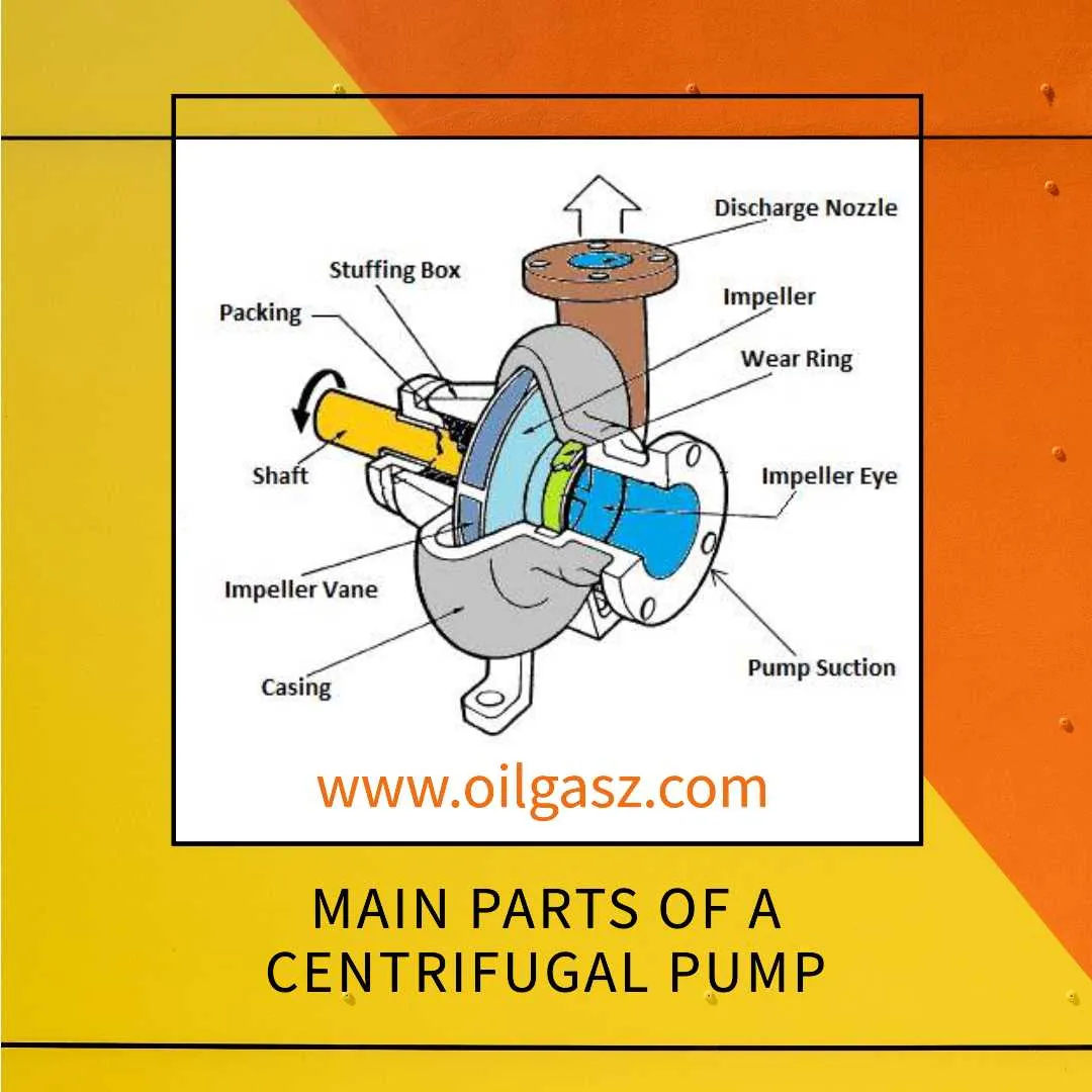
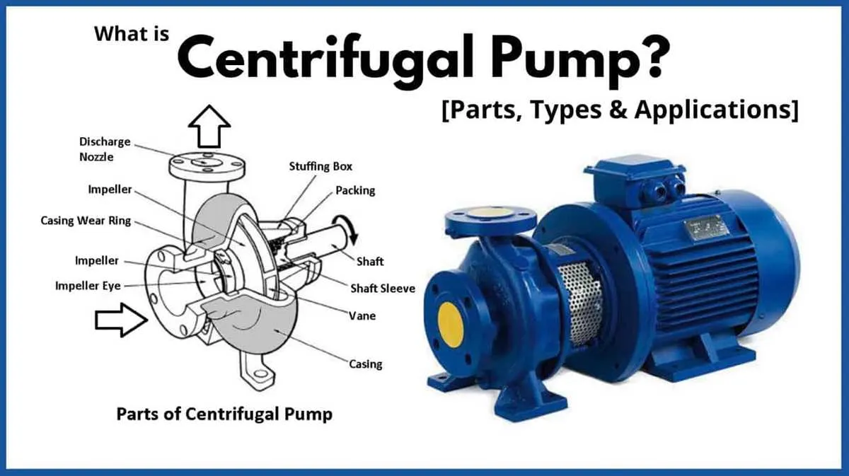
Understanding the layout of a rotational flow machine is essential for optimizing its efficiency. The main components are designed to convert mechanical energy into fluid flow and pressure. Key elements include:
- Impeller: The rotating element that accelerates the fluid. It is typically made of metal or composite materials and is characterized by blades that direct the fluid outward.
- Volute: A spiral-shaped casing that collects the fluid after it exits the impeller, converting velocity into pressure.
- Diffuser: A set of stationary vanes that guide the fluid flow, helping to reduce turbulence and enhance pressure recovery.
- Suction and Discharge Ports: Entry and exit points for fluid, crucial for maintaining optimal flow conditions and ensuring minimal resistance.
Each part is strategically positioned to ensure smooth fluid transition and minimal energy loss. The fluid enters the machine through the suction port, is accelerated by the impeller, and exits at high velocity, which is then converted to pressure in the volute or diffuser section.
Effective design requires balancing the impeller size, blade angle, and casing geometry to minimize friction losses and maximize throughput. Regular maintenance and monitoring of these components can significantly improve performance and longevity.
Components and Their Functions in a Pump System

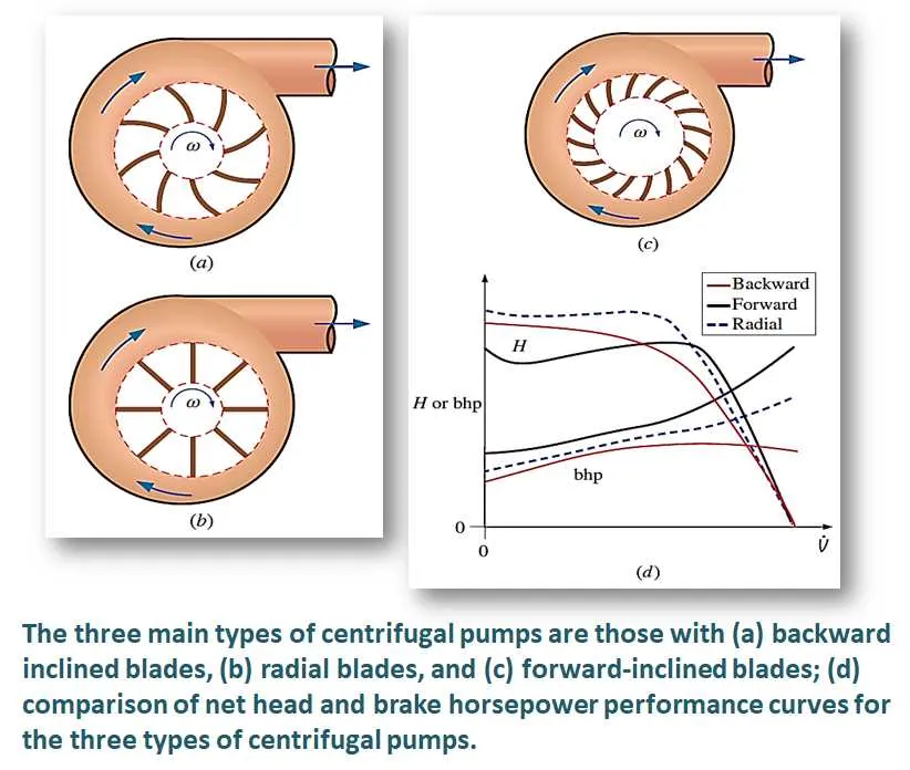
The impeller is the core element that converts mechanical energy into kinetic energy. Positioned within the casing, it rotates and accelerates the fluid, directing it outward. The shape and number of blades affect performance, influencing both flow rate and pressure.
The casing serves as a containment structure, guiding the fluid as it moves through the system. Its design helps in directing flow and maintaining pressure, with variations in shape tailored to specific operational needs.
The suction inlet draws fluid into the system, typically at low pressure. This component must be properly sized to avoid cavitation, a phenomenon that can lead to damage and reduced efficiency.
The discharge nozzle directs the flow out of the system, usually at a higher pressure. Its design and placement impact the velocity and pressure of the fluid, affecting system efficiency.
Bearings support the shaft, ensuring smooth rotation and minimizing friction. They also help maintain alignment of the rotating components, contributing to longevity and reliable performance.
The shaft connects the impeller to the motor or driver, transmitting rotational force. It must be strong enough to withstand the stresses of rotation without bending or breaking.
The diffuser reduces the velocity of the fluid as it exits the impeller, converting kinetic energy into pressure. It helps improve overall system efficiency by ensuring smoother flow toward the discharge nozzle.
The volute is a spiral-shaped casing that collects the fluid after it passes through the impeller. It helps convert kinetic energy into pressure, improving the system’s overall hydraulic efficiency.
Seals prevent fluid leakage and protect internal components from corrosion. They are critical for maintaining system integrity, especially in high-pressure or high-temperature environments.
The motor or driver provides the mechanical power necessary to rotate the impeller. Its size and power rating must be carefully matched to the requirements of the system to ensure optimal performance.
How to Interpret Flow Directions and Pressure Distribution in the Diagram
Flow direction is critical for understanding the system’s behavior. The arrows represent the motion of the fluid, starting from the inlet and moving towards the outlet. In a well-designed system, the flow should be steady and smooth, without significant turbulence. Analyzing these arrows helps identify whether the fluid moves in a radial, axial, or mixed direction. Pay close attention to any deviations or irregularities that may indicate issues like cavitation or flow instability.
Pressure distribution is usually depicted with contour lines or color gradients. These indicate areas of higher and lower pressure throughout the system. In the region where the fluid is accelerated (typically near the inlet and at the center), pressure will be lower. As the fluid moves outward, pressure increases due to the centrifugal force. The pressure rise near the outer edges can help in assessing the energy imparted to the fluid. A uniform pressure distribution suggests good design, whereas sharp variations may indicate inefficiencies or potential design flaws.
Always look for areas where the pressure drops rapidly. These zones can be prone to cavitation, causing damage or loss of efficiency. Understanding the pressure profile across different points ensures the system is operating within acceptable performance limits.
Common Troubleshooting Insights from Pump Diagrams
For issues with low discharge pressure, check the impeller for damage or wear. A worn impeller reduces the ability to move fluid efficiently, leading to a drop in pressure. Also, ensure the suction line is not clogged or obstructed, which can impede flow into the unit.
If vibrations are excessive, verify the alignment of the motor shaft and pump shaft. Misalignment can lead to uneven wear on bearings, which often results in vibrations. Tightening the coupling between the shafts might resolve the issue.
For reduced flow rates, inspect the suction strainer for debris. Blockages here restrict fluid intake, lowering the overall output. Additionally, check for air leakage in the suction line, which can lead to cavitation and decreased performance.
In cases of high power consumption, evaluate the bearing and seal condition. Overheating of bearings or damaged seals can increase friction, requiring more energy to maintain operation. Lubrication levels should also be inspected regularly.
To prevent cavitation, ensure the inlet pressure is high enough and the system operates within the recommended NPSH (Net Positive Suction Head) limits. Inadequate NPSH is a primary cause of cavitation, damaging components and reducing efficiency.