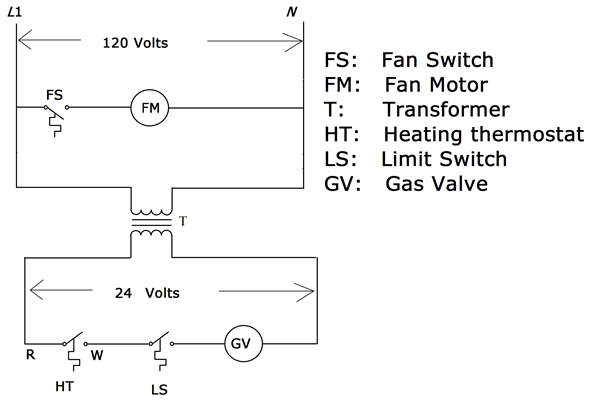
View and Download Honeywell TC installation instructions manual online. Typical wiring diagram for TC on zone 1 ENGAGE TABS AT TOP OF.
INSTALLATION. When Installing this Product 1. Read these instructions carefully.
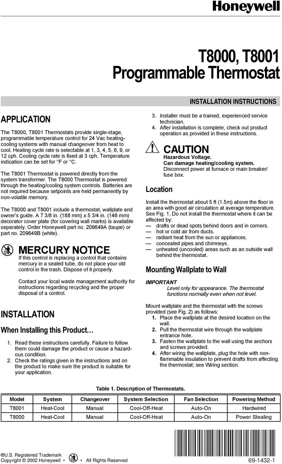
Failure to follow them could damage the product or cause a hazard-. there are any,sometimes the t-stat is hard wired in and there are no batteries – TC, TC, TR |TC Programmable. In Canada—Honeywell Limited/Honeywell Limitée, 35 Dynamic Drive, .
O. Fig. 8.
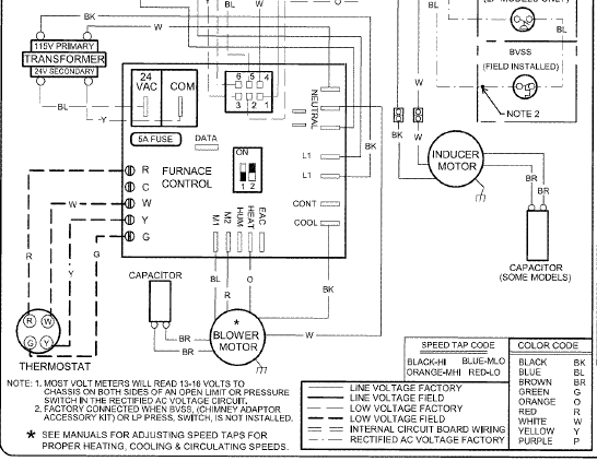
TC wiring diagram in heat-cool TC heat-cool wiring diagram on a. I have a TC Honeywell thermostat.
If you removed the thermostat to expose the subbase and wiring and used a paperclip bent into a U shape and held it on R . Show mu on the diagram and/or what color are they?.TB,C AN ELECTRONIC ROUND PROGRAMMABLE THERMOSTAT 5 —1 Fig.
7. TC heat-cool wiring diagram in single trans-former system with gas or electric heat/electric cooling.
Fig. 9. TB Heat Only wiring diagram in electric baseboard or ceiling cable system.
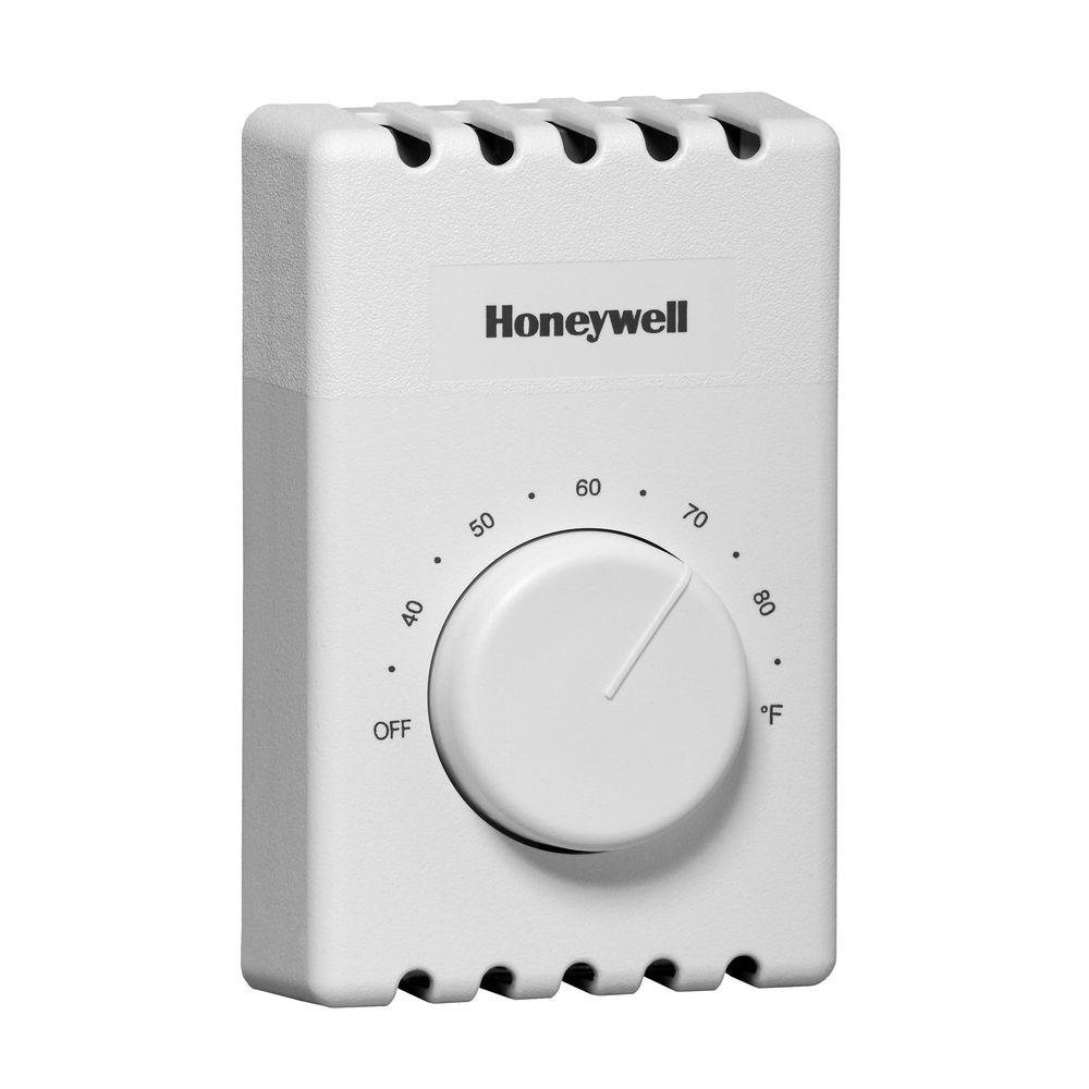
Fig. 8.
TC heat-cool wiring diagram in oil heating/electric cooling. Other thermostats have fewer wires.
Again referring to the Honeywell thermostat ct31a wiring diagram, you can see it requires only two wires, R and W. It doesn’t control cooling and, because it’s a mechanical thermostat, it doesn’t need power for internal functions, so it has no C wire. Honeywell Tc thermostats are designed to be simple and trouble-free.
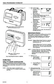
The control panel is extremely straightforward and its no-nonsense operation emphasizes longevity over a lot of bells and whistles. TC PROGRAMMABLE THERMOSTAT Fig. 7.
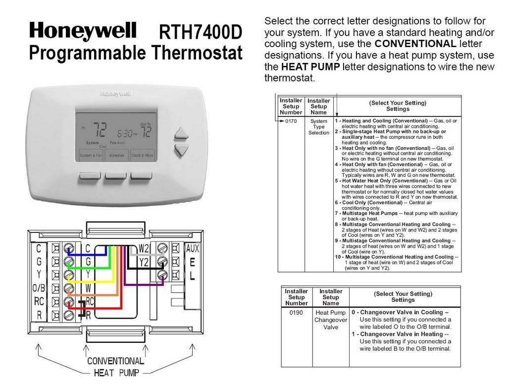
Typical wiring diagram for TC on zone 1 MABS II/L control panel. Setting Fan Operation (Fuel) Switch The fan operation (fuel) switch is preset at the factory in the F position.
See Fig. 8. This is the correct setting for most systems.
If this system is an electric heat system, set the switch to the E. Fig.
9. TC heat-cool wiring diagram in single transformer system with gas heat/electric cooling. Fig. 6.
TC heat-cool wiring diagram in single transformer system with gas heat/electric cooling. Fig. 7.
Honeywell T8000c Wiring Diagram
TC wiring diagram in heat/cool system with two transformers. Y G Rc W R 2 4 B O M L1 (HOT) L2 FAN RELAY HEAT RELAY L1 (HOT) L2.SOLVED: TC Honeywell – fuses???
– FixyaSOLVED: Honeywell TC Thermostat Problem – Fixya