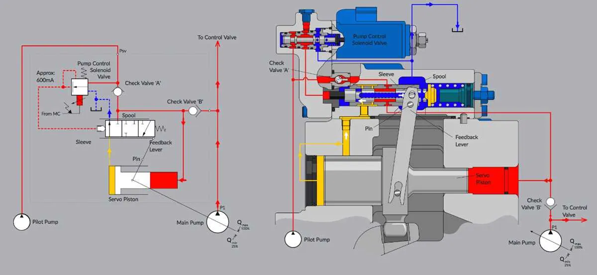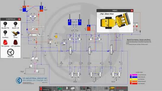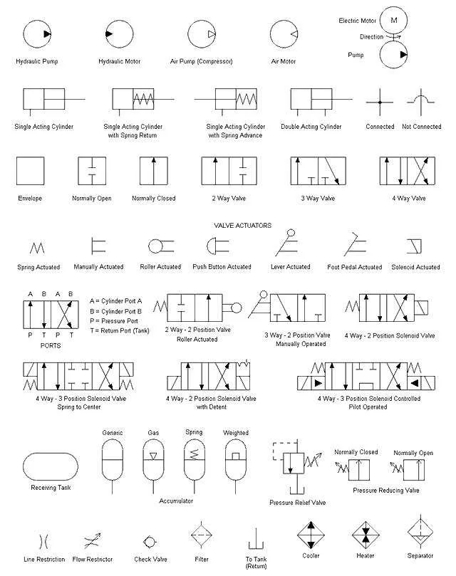
When working on fluid power system layouts, choosing the right tool is crucial. For efficient creation and analysis of schematics, opt for platforms that offer intuitive interfaces and comprehensive libraries. These applications allow for precise placement of components like pumps, valves, and actuators, ensuring an error-free and easily understandable final design.
Among the most essential features to look for are simulation capabilities. Being able to test how the system behaves under different conditions before physical implementation can save significant time and resources. Look for tools that integrate with real-time data from physical setups, offering the flexibility to adjust components based on performance feedback.
For those involved in complex multi-phase systems, seek programs that support 3D modeling. This visual enhancement not only improves the accuracy of layouts but also ensures compatibility between different system parts. Additionally, a program with robust export options, like AutoCAD or DXF files, can streamline collaboration across various stages of development.
Consider software with cloud-based features for seamless access and collaboration among team members across locations. This provides flexibility and ensures that all modifications are updated in real time, minimizing the risk of errors during system integration.
For simplicity and power in your designs, invest time in familiarizing yourself with the platform’s advanced features such as pressure drop analysis, flow rate calculations, and system optimization tools. These will not only enhance your productivity but also ensure the systems you design are both efficient and cost-effective.
Choosing the Right Tool for Designing Fluid Systems
Opt for a design tool that allows for precise simulation and integration of components like pumps, valves, and actuators. A robust platform should provide drag-and-drop functionality for easy assembly and accurate representation of components. Look for real-time feedback on system performance, including pressure, flow, and energy consumption. Seamless integration with CAD tools will improve workflow efficiency, while offering the ability to export designs in standard formats. Ensure that the tool supports customizable libraries for specific components and offers both 2D and 3D viewing options for enhanced analysis. Focus on ease of use and compatibility with industry standards.
For fluid power systems, look for solutions offering predefined templates and system-specific blocks, as they simplify the initial setup process. Additionally, simulation features that test the behavior of your design under various conditions are crucial for verifying the performance before physical implementation. Advanced tools include the ability to simulate different fluid properties, and offer detailed results on efficiency and performance. Check for automatic error-checking capabilities to avoid issues in the early design phases, which can save both time and resources.
Another essential aspect is collaboration. Choose a tool that facilitates real-time teamwork by allowing multiple users to work on the same project simultaneously. Cloud-based platforms can enhance this feature, ensuring accessibility from any location. This is particularly beneficial for teams spread across multiple locations or those working on large-scale projects.
Cost efficiency should not be overlooked. While advanced tools come with a higher price tag, many offer scalable plans or trial versions. Test the platform’s ease of implementation and support before committing to a long-term investment. Consider platforms that provide excellent customer support and comprehensive tutorials to help onboard new users quickly.
How to Choose the Right Tool for Designing Fluid Systems

When selecting a tool for designing fluid systems, prioritize flexibility and ease of integration with other engineering applications. Look for platforms that support industry-standard symbols and components, allowing you to quickly build complex designs without manually adjusting elements. Compatibility with different file formats, such as DXF and SVG, ensures seamless collaboration with colleagues or clients using various design tools.
Ensure the application offers intuitive drag-and-drop functionality for placing components. The more predefined blocks and connections it includes, the less time you’ll spend on repetitive tasks. Also, check if the tool has built-in validation features to automatically detect potential issues in your layout, reducing the likelihood of errors during the design process.
Consider platforms with advanced simulation capabilities, enabling you to test how fluid flows through the system and verify performance before physical implementation. These simulations should allow for the analysis of pressure, flow rates, and other critical factors in real-time. Also, choose a solution with cloud support if remote collaboration is essential for your team.
Finally, evaluate the learning curve. While advanced tools may offer more features, they often require extensive training. If your team needs to start working quickly, opt for a user-friendly interface, even if it means sacrificing a few advanced functionalities. An effective tool should strike a balance between simplicity and the ability to meet the specific demands of your projects.
Key Features to Look for in Hydraulic System Design Tools

When choosing a tool for designing fluid power systems, prioritize the following features:
- Intuitive Interface: The design process should be seamless, with easy access to necessary components and quick placement options. Avoid cluttered layouts.
- Predefined Components Library: A comprehensive set of ready-made symbols for pumps, valves, actuators, and other parts is essential. The library should be regularly updated to reflect industry standards.
- Advanced Simulation Capabilities: The ability to run simulations and visualize real-time behavior under various conditions is critical for accuracy. Look for tools with integrated flow and pressure analysis.
- Customizable Components: The ability to modify or create custom symbols and elements allows for adaptation to specific system requirements.
- Compatibility with Industry Standards: Ensure the tool supports common industry formats for easy sharing and collaboration, such as ISO, ANSI, and JIS standards.
- Integration with CAD Programs: Integration with major CAD systems allows for easy transfer of designs between platforms, which is crucial for larger projects.
- Real-Time Data Import: Some tools can import real-world data to simulate actual performance, enhancing design accuracy.
- Cost Estimation and Reporting: A feature that generates cost estimates based on components used in the design can help in budgeting and procurement planning.
- User Collaboration Features: Multi-user access and cloud integration ensure smooth collaboration between engineers and stakeholders, even remotely.
- Cross-Platform Support: Choose a platform that works across various operating systems, such as Windows, MacOS, or cloud-based solutions, for greater flexibility.
Common Mistakes to Avoid When Using Fluid System Design Tools
Do not overlook the importance of accurate symbol selection. Using the wrong icon for a component can lead to confusion and incorrect system representation. Always ensure you are using standardized and recognized representations for each part to maintain clarity and avoid costly errors.
Ensure all connections are clearly defined. Often, users neglect to check for proper linking between components, which can cause logical issues during the simulation or analysis. Double-check that every part is correctly connected to prevent system malfunctions or unrealistic results.
Do not neglect pressure drop calculations. Many overlook how flow resistance affects performance, which can result in inaccurate sizing or inefficient system operation. Integrate calculations for pressure loss in pipes, valves, and other components to enhance accuracy.
Be cautious when scaling components. Misinterpreting size requirements for valves, pumps, or actuators can lead to system overdesign or underperformance. Always match component specifications to your project’s operational demands, ensuring proper capacity and functionality.
Regularly validate input parameters. Users often assume default settings are correct for their specific project, which can skew results. Input parameters such as fluid properties, operating pressures, and temperatures must be tailored to the specific application for precision.
Avoid cluttering your workspace with unnecessary elements. Excessive detail can make it harder to spot key issues and complicate system troubleshooting. Focus on the core components and relevant connections to keep the design clean and easy to follow.
Don’t skip thorough testing. After completing the layout, run simulations to verify the system functions as intended. It’s easy to assume that everything is correct without running these tests, but errors often arise when it’s too late to make adjustments.
Finally, always document changes. When modifying a design, keeping track of revisions is crucial for future reference and troubleshooting. Clear annotations can save significant time when revisiting the project at a later stage or for maintenance purposes.