To optimize the performance of your filtration unit, it’s crucial to understand the essential components that contribute to its efficiency. The process begins with the initial phase where minerals responsible for hardness are removed through a resin bed. This mechanism operates through ion exchange, swapping calcium and magnesium ions with sodium ions, effectively reducing scale buildup in your pipes and appliances.
Once the system is saturated with hardness ions, a regeneration cycle is initiated. During this phase, a highly concentrated saline solution flushes through the resin, displacing the accumulated minerals. This step ensures the continued effectiveness of the unit and allows it to operate without diminished capacity.
The unit typically features a control valve that manages the flow of both influent and effluent, directing the flow based on specific needs such as regeneration or regular filtration. Regular maintenance of this valve and resin bed is essential to ensure uninterrupted service and to prolong the lifespan of the equipment.
Proactive monitoring of performance indicators such as pressure and flow rate is recommended. This helps in identifying potential issues before they escalate, saving time and money on repairs or replacements. Keep track of the system’s salt levels to prevent it from running dry, which could lead to inefficiency and potential damage to the resin bed.
How a Filtration System Works
Install a filtration unit with a resin tank to remove hardness-causing minerals like calcium and magnesium. The process begins with a pre-treatment phase, where hard elements are captured by ion-exchange resin beads. The beads exchange sodium ions for the magnesium and calcium ions, which are flushed away during regeneration.
Ensure regular regeneration to maintain effectiveness. During regeneration, the beads are washed with a saline solution to replace the sodium ions and remove the accumulated hardness. The saline solution is then flushed out, making the beads ready for the next cycle.
For efficiency, monitor flow rates to avoid overloading the system. Consistent maintenance, including resin replacement every few years, ensures longevity and optimal performance of the unit.
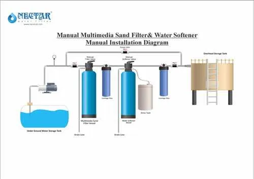
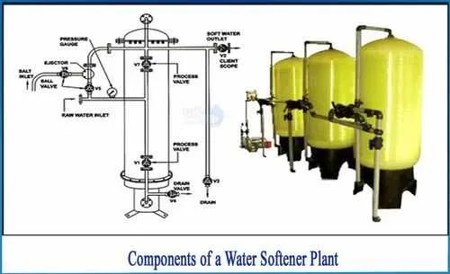
How to Read a Water Purification System Layout: Key Components and Their Functions

Start by identifying the flow paths and components that manage mineral removal. Understanding each part of the system ensures proper maintenance and efficient operation.
- Control Valve: The central unit that regulates the flow of liquid through the entire system. It is responsible for initiating regeneration cycles and monitoring pressure levels.
- Mineral Tank: This container holds the media responsible for trapping unwanted ions like calcium and magnesium. It is a vital part of the ion-exchange process.
- Brine Tank: A reservoir that stores a salt solution used to recharge the resin inside the mineral tank. The brine tank is automatically replenished as needed during regeneration.
- Resin Beads: Tiny, spherical particles inside the mineral tank. These beads attract and hold onto hard minerals, exchanging them for sodium ions during regeneration.
- Drain Line: This line carries away waste water during the backwash and regeneration processes. It is essential for maintaining the system’s efficiency.
- Bypass Valve: Allows you to bypass the filtration process if needed. This feature is useful during maintenance or when the system is not in use.
Check for arrows indicating flow direction; they show the sequence of processes and where each component comes into play. Regular monitoring of the resin tank and brine level ensures smooth operation.
Use the layout to pinpoint potential issues, like blockages or leaks. Proper understanding of each component aids in troubleshooting and improves system longevity.
Step-by-Step Process Flow in a Water Treatment System

The first stage involves the entry of untreated fluid into the system, where a pre-filtration step removes larger particles and debris. This prepares the liquid for subsequent treatment. The next step directs the flow through a resin bed, where minerals such as calcium and magnesium are exchanged for sodium ions. This ion-exchange process reduces hardness by replacing problematic elements with more manageable ones.
Once the fluid passes through the resin, it continues to a regeneration tank. Here, a salt solution is introduced to cleanse the resin bed, restoring its effectiveness for future cycles. The saturated brine displaces the accumulated minerals, which are flushed out as waste during the regeneration process. The system then enters a standby mode, awaiting the next cycle of treatment.
After the regeneration phase, the fluid moves to a final filtration unit that ensures any remaining particulates or impurities are removed before distribution. This step guarantees that the treated liquid is free from any residual contaminants. Finally, the now-treated liquid flows into the designated storage area, ready for use or distribution within the facility.
Common Troubleshooting Tips Based on the System Layout
Check for clogs in the inlet valve if the system isn’t filtering effectively. This can prevent proper flow and affect regeneration cycles. Ensure the valve is clear of debris or sediment buildup.
If the system isn’t regenerating, inspect the timer or control board for any malfunctions. A faulty timer may fail to initiate regeneration, disrupting the salt exchange process. Reset or replace if needed.
Examine the brine tank for excessive salt or a hardened salt bridge. If present, break up the bridge and clean the tank to allow proper salt dissolution during the recharge phase.
Verify the bypass valve settings. If the system is bypassed during troubleshooting, it won’t treat the incoming supply, which can lead to confusion during maintenance. Make sure it’s correctly positioned for treatment flow.
Inspect the resin bed for wear or damage. If the resin beads are exhausted, the system won’t remove hardness effectively. Regeneration frequency might need to be increased, or resin should be replaced.
If you notice a decrease in water pressure, check for blockages in the filter screens or within the resin tank. These blockages can restrict flow and reduce system performance.