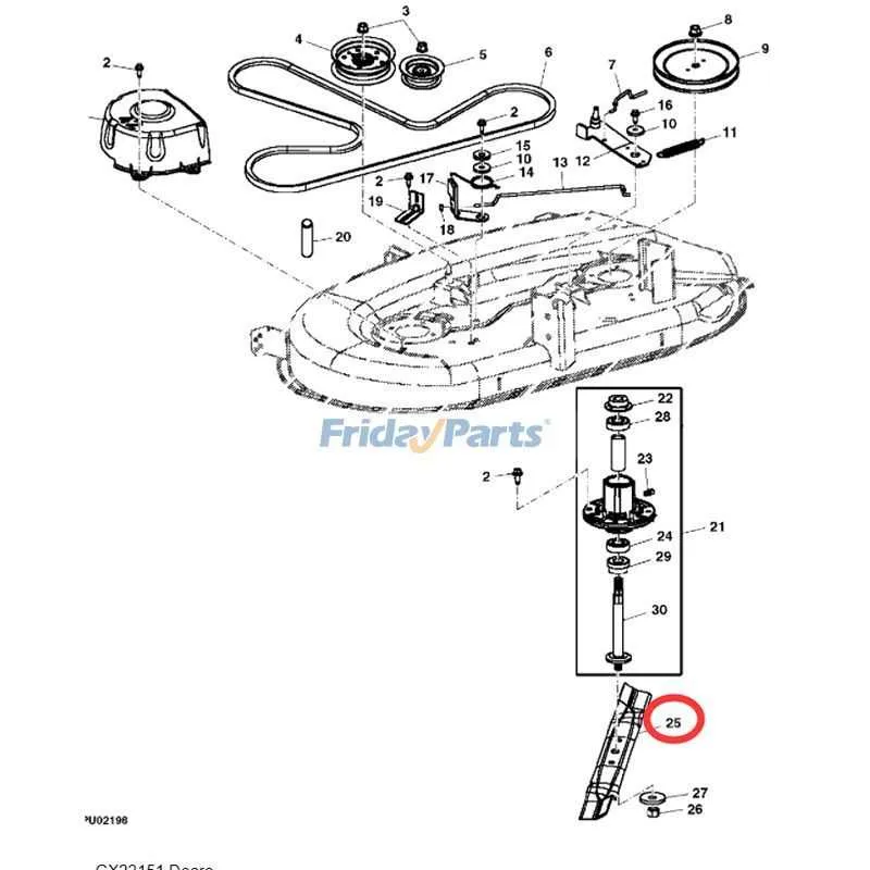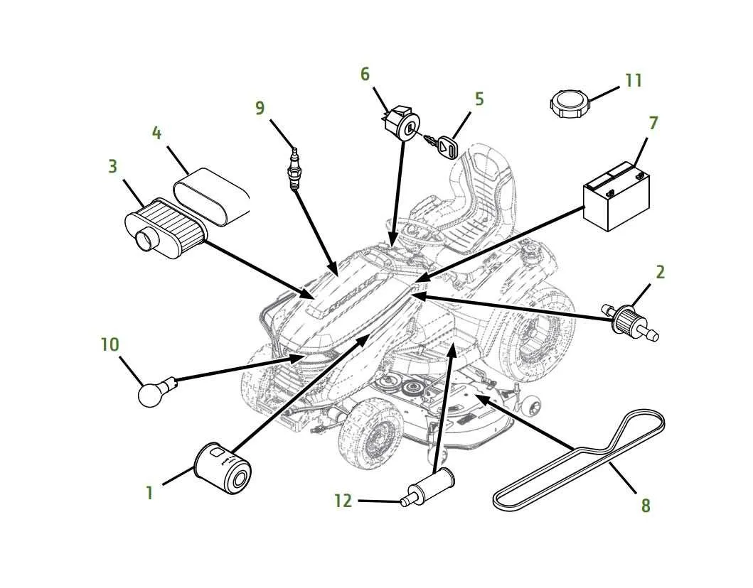
Locate the precise assembly illustrations to ensure accurate identification of every component within this lawn tractor model. Utilizing detailed exploded views allows quick access to individual units such as the engine parts, cutting deck assemblies, and transmission elements without guesswork.
Referencing authentic technical blueprints streamlines repair tasks, reducing downtime and avoiding unnecessary replacements. These schematics clarify the positioning and interconnection of mechanical and electrical pieces, enabling precise troubleshooting.
For optimal servicing, consult updated visual guides that highlight part numbers and connection points, enhancing the accuracy of ordering replacements. Relying on these resourceful layouts enhances both routine maintenance and complex restoration efforts.
Detailed Component Schematics for the D105 Model
For efficient maintenance and repair of the D105 mower, consult the comprehensive assembly blueprints available for each module. These illustrations provide precise part identification and placement, ensuring accurate servicing.
- Engine Assembly: Exploded view highlighting all engine elements including carburetor, air filter, and ignition system for quick troubleshooting.
- Transmission Setup: Visual guide to gearboxes, belts, pulleys, and associated linkages, simplifying replacement or adjustment procedures.
- Cutting Deck: Layout displaying blades, spindles, and mounting hardware to streamline blade swaps and deck repairs.
- Steering Mechanism: Diagram detailing steering rods, tie rods, and wheel hubs to facilitate precise alignment and part swaps.
- Electrical System: Wiring layout mapping out battery connections, switches, and ignition wiring for accurate diagnostics and wiring repairs.
Utilizing these schematics reduces downtime by enabling identification of exact components and their correct assembly order. Reference numbers and labels within the illustrations correspond to the official parts catalog, making ordering replacements straightforward.
- Locate the relevant schematic based on the malfunctioning subsystem.
- Identify the exact component using the exploded view.
- Cross-reference the part number for ordering or inventory check.
- Follow the assembly sequence indicated to avoid installation errors.
Access to these detailed visual guides is crucial for any technician or owner aiming for precise repairs without guesswork or unnecessary part replacement.
How to Identify Key Components in Equipment Schematics
Begin by locating the engine assembly section, often marked with numbers around 100-150. This area includes the motor block, air filter, and fuel system elements. Pay attention to exploded views showing bolts and seals–these help distinguish mounting hardware from moving parts.
Next, focus on the transmission cluster, typically detailed near the lower half of the schematic. Look for the drive shaft, pulley assemblies, and belt paths. The diagram uses distinct labels for tensioners and idlers, crucial for maintenance or replacement tasks.
Hydraulic and steering components are grouped together, with lines indicating fluid routes. Identifying reservoirs, pumps, and valves is easier by following arrows that denote flow direction. Cross-reference part numbers with the legend to ensure accuracy.
For cutting mechanisms, check for blade assemblies and spindle housings, usually shown with associated fasteners and bearings. These parts are frequently highlighted with exploded sectional views for clarity.
Electrical elements appear as separate clusters with wiring harnesses, switches, and connectors. Symbols like circles or squares denote connectors; tracing these connections helps in troubleshooting circuits effectively.
Finally, verify all components against the index or legend provided with the schematic. This step confirms part codes and prevents confusion between similar-looking items, streamlining repairs or ordering replacements.
Using Component Schematics to Troubleshoot Common Model D105 Issues

Locate the mower deck assembly illustration to identify worn or damaged belts causing uneven cutting. Cross-reference the drive system blueprint to inspect idler pulleys and tensioners for proper alignment and wear. If the engine fails to start, consult the ignition circuit layout to verify spark plug connections and coil integrity.
For hydraulic leaks, examine the transmission section schematic focusing on seals and hoses that often degrade. Refer to the fuel system map to pinpoint clogged filters or faulty fuel lines when experiencing performance drops. Electrical faults commonly arise from loose connectors shown in the wiring layout; trace all wiring paths to detect corrosion or breaks.
Use the steering mechanism sketch to check for binding or excessive play, which can be traced back to worn bushings or linkages. Cooling system problems can be diagnosed by reviewing the radiator and fan assembly diagram for blockages or belt slippage. Consistently compare the physical components with their illustrated counterparts to ensure no parts are missing or installed incorrectly during maintenance.
Step-by-Step Guide to Ordering Correct Replacement Components for Model D105
Begin by identifying the exact serial number of your equipment, usually located on the frame near the engine or under the seat. This ensures compatibility when selecting new elements.
Consult the official manufacturer’s catalog or an authorized digital manual specific to model D105 to locate part numbers and detailed assembly illustrations. Use these references to confirm the component designation and configuration.
Cross-check the required item numbers against the machine’s maintenance log or service records to verify wear patterns and previous replacements. This helps avoid ordering redundant or incompatible units.
Utilize authorized dealer websites or verified suppliers that provide authentic OEM components. Input the serial number and component codes for precise matching, reducing the risk of receiving incorrect items.
When ordering, specify any additional specifications such as color codes, material types, or version updates listed in the manual, to ensure the replacement matches factory standards exactly.
Keep a detailed record of all reference numbers and supplier confirmations. This documentation facilitates warranty claims and future maintenance scheduling.