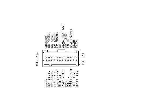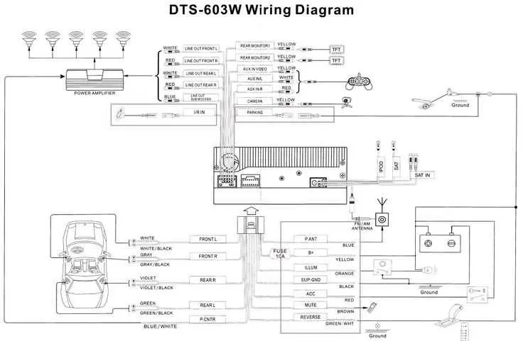
To properly connect your vehicle’s sound system, start by identifying the necessary connections between the head unit and the car’s electrical system. Ensure you have the proper wire harness for your model, which should match the factory connectors.
First step: Verify the power and ground wire connections. These are essential for the functioning of the audio system, and ensuring a secure ground connection will prevent audio issues.
Second step: Focus on the speaker wire assignments. Knowing the exact pinout for the speaker channels will guarantee that your speakers are wired correctly, avoiding damage and maximizing sound quality.
Next, pay attention to the amplifier connections if you’re adding one to your setup. Make sure you have a proper power wire to support the increased power draw, as well as an appropriate signal line.
Lastly, use a multimeter to check the integrity of all connections. This will help you avoid common wiring issues and ensure the system functions as intended.
Wiring Details for Your Truck’s Sound System
Start by identifying the power source for the sound unit. The constant 12V is typically connected to the orange wire, while the ignition-controlled 12V is generally tied to the red wire. These two are essential for powering the unit and ensuring it operates only when the ignition is on.
For ground connections, the black wire should be routed to a reliable metal point on the chassis. Make sure it’s a clean, unpainted surface for proper grounding.
Speaker connections follow a distinct pattern. The front left channel is usually connected through a green wire, while the front right uses a purple wire. Rear channels typically use light blue and dark blue wires, respectively. Confirm that the wires are securely connected to prevent any audio dropout.
Use a multimeter to double-check the connections. Test the 12V lines and ground with the vehicle powered on, ensuring the power and speaker channels have the correct voltage output. This step ensures you’re working with a properly functioning setup.
If you’re adding additional equipment like amplifiers, the blue wire often serves as an accessory for turning on those devices. Make sure you connect this properly to avoid any malfunction.
Understanding the Pinout for the 2004 Chevy Silverado Audio System

Start by verifying the connector’s orientation to avoid improper connections. The harness typically includes power, ground, speaker outputs, and antenna connections. Each pin in the connector corresponds to a specific function that must be matched correctly to ensure proper system operation.
For power connections, locate the 12V constant power, usually marked as pin 1 or 2 in the plug. This provides continuous power to the system, even when the ignition is off. The ignition-switched 12V wire is often positioned next to the constant power and should be connected accordingly to enable the system when the key is turned on.
Ground wires are essential to complete the circuit. Typically, the ground connection is located at pin 4 or 5 and should be connected directly to the vehicle’s chassis or a known ground point.
Speaker outputs are organized in pairs. Each pair of pins controls the left and right speaker channels, with the positive and negative terminals clearly defined for each side. Commonly, the front left and right speakers are located at pins 6 and 7, while the rear left and right are found at pins 8 and 9. Ensure you match each pair to its corresponding speaker to avoid phase issues.
The antenna signal is crucial for radio reception, and the antenna lead is typically on pin 3. This connection should be secure to ensure optimal signal strength for the reception of AM and FM channels.
Double-check all connections with a multimeter for continuity before final installation. Miswiring can cause system malfunctions or damage components, so precise attention to pinout details is crucial.
How to Identify Power and Ground Wires in the Vehicle Harness
Start by locating the connector that links to the audio system. Power and ground wires are typically standardized in most car setups, so once identified, you can be sure of their function. Here’s a quick guide to determine which wires provide power and which serve as ground connections.
- Power Wire: Usually red or yellow in color, this wire supplies constant power to the unit. If the wire is yellow, it indicates the constant 12V line, while red is often used for the switched 12V line.
- Ground Wire: This is typically black. It connects to the vehicle’s chassis and completes the electrical circuit.
- Test for Power: Use a multimeter to confirm the power source. Set the multimeter to DC voltage, place the negative probe on a known ground, and check the voltage on the suspect wires. A reading of 12 volts indicates a power wire.
- Test for Ground: With the multimeter set to measure continuity, check between the wire and any metal part of the car’s frame. A signal indicates a ground connection.
Once you confirm the wires, connect them carefully to ensure a secure, stable electrical connection. Incorrect wiring can lead to malfunction or damage to the system.
Step-by-Step Guide to Replacing the Audio System Connections in Your Truck
To replace the audio system connections, follow these precise steps for a successful installation.
1. Disconnect the vehicle’s battery to prevent any accidental shorts while working with electrical components.
2. Remove the dashboard panel covering the stereo. This might involve unscrewing several bolts or clips depending on the truck’s design.
3. Carefully extract the old unit from its mounting. You may need a trim removal tool to avoid damaging the dashboard trim.
4. Identify and label each connector on the back of the unit to ensure proper reconnection. There will typically be connectors for power, ground, speakers, and additional features such as an antenna or aux input.
5. If needed, cut and strip the necessary cables for the new system. Use crimp connectors or solder the connections for a secure fit. Make sure that all wires are clearly marked and insulated to prevent shorts.
6. Install the new head unit by connecting the wires in accordance with the labels or the new unit’s instructions. Ensure all connections are tight and free from loose strands that could cause malfunctions.
7. Secure the unit in place and reattach the dashboard panel, ensuring all clips and screws are properly aligned.
8. Reconnect the battery and test the system to ensure all functions, such as sound output, volume control, and power, are operating as expected.
By following these steps, you can confidently replace your system’s connections and restore full functionality without complications.