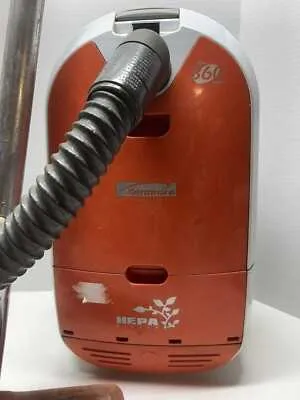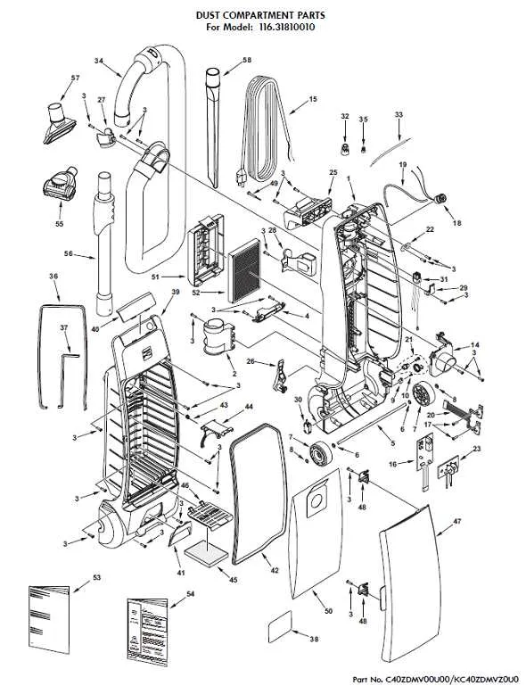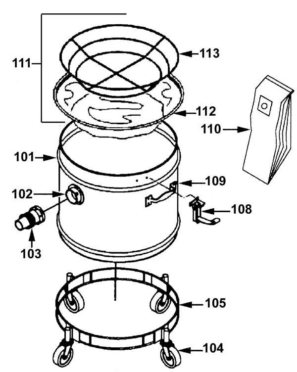
Start by inspecting the intake assembly, which typically includes the motorized brush, belt, and front housing. A visual schematic will show the precise alignment of the agitator brush and its bearings–these are common wear points. If the unit is not picking up debris effectively, a worn drive belt is often the culprit.
Next, examine the airflow channel and filtration compartment. Refer to the layout to locate the pre-motor filter, post-motor filter, and internal ducts. Ensure the seals and gaskets are intact; leaks in this area reduce suction and can lead to overheating.
The electrical layout reveals the placement of the control switch, circuit board, and motor terminals. A burned-out thermal fuse or corroded wire connector is often the reason behind sudden power loss. Use the wiring chart to trace each connection precisely before replacing any internal electrics.
Finally, focus on the base plate and structural supports. These include axle mounts, caster wheels, and lower housing fasteners. The schematic helps identify screw sizes and mounting brackets to avoid damaging plastic slots during disassembly. Always follow the exact order of part removal and replacement to maintain proper alignment.
Component Breakdown for Unit 115

Start with inspecting the powerhead assembly–look for brushroll wear, broken belt, or debris obstructing the agitator. A cracked nozzle housing or worn end caps may also compromise cleaning performance.
Next, examine the suction motor compartment. Replace carbon brushes if sparking occurs or airflow drops significantly. Ensure the motor mount cushions are intact to reduce vibration.
Focus on the dust chamber and filtration route. Swap the HEPA cartridge or foam element regularly to maintain airflow. Cracks in the dust container or lid latch can lead to leaks–replace them promptly.
Inspect the wand and handle connections for secure locking tabs. A damaged swivel neck or loose telescoping mechanism can hinder maneuverability–substitute faulty sections with OEM-compatible tubing or couplers.
Check the wiring harness running through the hose and handle. Broken terminals or insulation wear near the switch can cause intermittent power–re-crimp or replace wire leads as needed.
How to Identify and Locate Components Using the Kenmore 115 Parts Diagram

Start by referencing the exploded schematic that corresponds to the exact serial code on your appliance label–usually found near the cord rewind or underneath the main chassis. This ensures accurate alignment between the visual layout and your specific unit.
Look for numbered callouts within the breakdown illustration. Each digit directly maps to a reference index below the diagram, where item names, stock codes, and positional data are listed. Prioritize assemblies first (like the motor housing or powerhead neck) to orient your search.
Use the sectional grouping–typically separated into motor compartment, hose connection, floor tool, and filtration chamber–to isolate the zone where your suspected faulty element belongs. For example, filters and seals are usually grouped in the exhaust chamber section, while agitator brushes and belts appear under the nozzle view.
Cross-check visual indicators like shape, bolt position, and slot orientation against your actual device before ordering replacements. If a component appears symmetrical in the schematic, verify alignment by counting screw points or measuring bracket angles in millimeters.
Always note sub-component hierarchies. Some fasteners or clips may not be labeled independently–they are bundled under a parent assembly. In these cases, a full kit must be sourced rather than individual pieces.
Commonly Replaced Parts in the Kenmore 115 and Their Diagram References

Replace the agitator brush roll when bristles show uneven wear or lose stiffness. Refer to diagram section A3 for proper orientation and fastening points.
Inspect the belt if the brush stops spinning or emits a burning smell. A worn or broken drive band is listed under diagram B2. Ensure correct tension during installation to avoid motor strain.
The exhaust filter should be swapped every six months to maintain airflow. Locate its housing in section C1, behind the rear panel. Always insert the new cartridge with the airflow arrow pointing outward.
For loss of suction, check the hose assembly for clogs or cracks. Diagram D4 illustrates attachment clips and routing channels. Secure all connections tightly to prevent air leaks.
If the power switch becomes unresponsive, replacement is necessary. Diagram E6 shows the switch module with wiring layout. Disconnect from power before attempting any internal electrical replacement.
The height adjustment wheel wears down over time, affecting floor contact. Diagram F2 identifies the elevation gear and spring assembly. Use correct alignment to prevent misleveling.
Where to Find Accurate Kenmore 115 Parts Diagrams for Repairs and Ordering

Start by visiting Sears PartsDirect, the most reliable source for exploded views and component listings. Use the product’s serial number or category filter to access detailed schematics specific to your unit.
- Encompass Supply Chain Solutions: Offers high-resolution blueprints and replacement items with OEM reference numbers. Search using the manufacturer’s prefix followed by the unit number.
- eReplacementParts.com: Browse through technical illustrations and assembly charts. Each sub-section includes pricing and compatibility info, streamlining the reorder process.
- AppliancePartsPros: Navigate to the “Diagrams” tab after entering the item code. Each view shows grouping by motor housing, hose assembly, and nozzle components.
- Manualslib.com: For archived service sheets and legacy unit references. Often includes breakdowns by motor chassis and suction control modules.
For discontinued or rare configurations, check forums like r/appliancerepair or the Vintage Appliance community on Facebook, where collectors share scanned overlays and maintenance visuals.