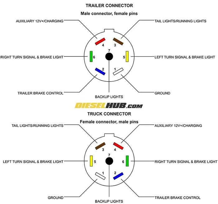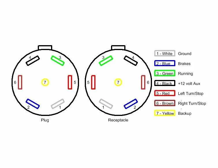
To ensure proper functionality, it’s essential to connect the seven pins of your towing system according to the standard pinout. Each terminal serves a specific purpose, ensuring signals are transmitted to the necessary components such as lights and brakes.
Pin 1: This is designated for the ground, providing a common return path for all electrical connections. Make sure this is securely connected to avoid any power issues.
Pin 2: This pin is used for the left turn signal. It should be wired to the corresponding left indicator of your vehicle.
Pin 3: The right turn signal is connected through this terminal. It corresponds with the right signal of your towing unit.
Pin 4: This terminal carries the brake light signal. Proper wiring ensures that your vehicle’s brakes are signaled to the connected load when applied.
Pin 5: This pin is typically used for auxiliary power or battery charge. It is crucial for keeping additional equipment powered during towing.
Pin 6: Used for the reverse light signal. It’s necessary to wire this pin to the reverse light of your connected vehicle to signal when reversing.
Pin 7: This terminal handles the 12V constant power supply, often used for running the electric brakes or other 12V-powered accessories.
By ensuring each terminal is properly assigned, you maintain the correct function of all towing components, providing safer operation and preventing damage to electrical systems.
Connection Setup for 7-Terminal Vehicle Connector

To properly connect a 7-pin socket to a vehicle, follow these terminal assignments:
- Terminal 1: Ground connection (White) – ensures proper functioning of the electrical system.
- Terminal 2: Left turn signal (Yellow) – activates the left-side indicator light.
- Terminal 3: Right turn signal (Green) – controls the right-side indicator light.
- Terminal 4: Brake lights (Red) – provides power to the braking lights on the attached unit.
- Terminal 5: Running lights (Brown) – keeps the lights on continuously when the vehicle is on.
- Terminal 6: Auxiliary power (Blue) – often used for powering accessories or backup functions.
- Terminal 7: Electric brake controller (Black) – ensures proper power flow to electric brakes.
Make sure to securely fasten all connections, as poor contact can result in malfunction or safety issues during operation.
Understanding the Pin Configuration of a 7-Pin Connector
The 7-pin connection is essential for vehicles towing heavier loads, allowing a reliable power transfer between the towing vehicle and the towed unit. Each of the seven pins has a specific function, and knowing how they work together ensures proper functionality. The pinout is usually arranged in a standard way, where each pin is dedicated to a particular circuit. Here’s a breakdown of the most common configuration:
The first pin typically handles the ground, providing a return path for the electrical current. The second one usually carries the left turn signal or brake light, while the third is assigned to the right turn signal or brake light. These two circuits are critical for indicating turns and stopping, both of which must be properly connected to avoid safety issues.
The fourth pin is commonly dedicated to the tail lights, ensuring that the rear of the towed unit is illuminated. The fifth slot is responsible for the auxiliary power, supplying a constant 12V source to power additional accessories on the towed unit, such as a refrigeration unit or electric brakes. The sixth pin generally manages the electric brake system, sending signals from the towing vehicle to engage the brakes on the towed unit when necessary.
The seventh pin serves to provide reverse lights, ensuring the towed unit’s visibility when reversing. This pin configuration is generally uniform, but it’s crucial to check your specific setup to confirm compatibility with your vehicle and equipment. Misconnections can lead to malfunctioning lights or even cause electrical damage, so always ensure each pin is correctly wired to its designated function.
Step-by-Step Guide to Wiring a 7-Wire Trailer Plug
Start by identifying the specific pins and their functions: Ground (white), Left turn and brake (yellow), Right turn and brake (green), Tail lights (brown), Auxiliary power (blue), Electric brakes (black), Reverse lights (purple).
Ensure you have a proper connector with sufficient space to accommodate all seven terminals. The metal prongs must be securely attached to prevent any loose connections during use.
Begin with the white wire, attaching it to the terminal designated for ground. This ensures a stable electrical return path.
Next, connect the yellow wire to the left turn signal and braking terminal. This will activate the left indicator and brakes when engaged.
Similarly, connect the green wire to the right turn signal and braking terminal, which powers the right indicator and braking system.
Attach the brown wire to the terminal for tail lights. This wire powers the rear lighting on your vehicle during night travel.
The blue wire should be linked to the auxiliary power terminal, used to charge a battery or provide power to other electrical components on the towed unit.
Link the black wire to the electric brake terminal. This provides the necessary current to control the braking system of the towed equipment.
Finally, attach the purple wire to the reverse light terminal. This will illuminate the reverse lights when backing up.
Double-check each connection for secure attachment and proper polarity. Make sure each wire is properly insulated to avoid short circuits.
Troubleshooting Common Electrical Issues in 7-Conductor Connectors
If the lighting or signal functions aren’t working properly, first check the connection points for any signs of corrosion or dirt. Clean them thoroughly with a contact cleaner to ensure a strong connection.
- Faulty Grounding: A poor ground connection is often the root of many issues. Ensure that the grounding terminal is securely attached to a clean, rust-free metal surface.
- Blown Fuses: Inspect the fuse box and replace any blown fuses. Use the correct amperage as specified by the system to avoid further damage.
- Damaged Terminals: Inspect each terminal for signs of wear or breakage. Replace any damaged terminals immediately. A poor connection here can cause malfunctioning lights or signals.
- Incorrect Pinout: Double-check that each conductor is correctly placed in the corresponding terminal slot. Incorrect placement often leads to lighting malfunctions or short circuits.
Testing each section individually can help isolate the source of the issue. Use a voltage tester to ensure proper voltage is being delivered to each function, and check the continuity of the circuit for any interruptions.
- Voltage Drop: If certain functions are dim or weak, check for excessive voltage drop due to faulty connections or corroded terminals.
- Connection Integrity: Make sure that each connection is tightly secured. Loose or improperly seated connectors are a common cause of intermittent functionality.
Finally, inspect the entire setup for any signs of physical damage or fraying. Any exposed conductor should be replaced to avoid shorts and potential hazards.