When working on the electrical system of high-performance vehicles, precision is crucial. For mechanics and enthusiasts, understanding the complete setup is key to ensuring proper functionality. Ensure that you have access to detailed electrical maps that show every connection and component layout. This not only helps with diagnostics but also ensures any modification or repair maintains the integrity of the original system.
Familiarize yourself with each component’s role in the powertrain and infotainment systems. Pay close attention to the fuse boxes, control units, and sensor wiring. If you’re looking to fix or upgrade systems such as lighting or audio, knowing the specific wire routes can prevent accidental damage. It’s also advisable to have a clear guide on the locations of grounding points and wire protection, as these can often be overlooked in complex builds.
When referencing these technical maps, always cross-check the voltage ratings and wire colors. Using incorrect voltage levels can cause long-term damage to sensitive electronics. Furthermore, ensure that each connection is secure and properly insulated to avoid shorts or power loss. Keep in mind that factory updates or changes in wiring layouts may affect older schematics, so be sure to obtain the most recent version available.
For those modifying or restoring such cars, ensure that any alterations remain true to the original design or are made with equivalent or better-quality components. Electrical systems in high-performance models often require specialized connectors and high-performance materials to ensure long-term reliability under extreme conditions.
Electrical System Overview for Sports Vehicles
For optimal performance, ensure that you have access to accurate electrical blueprints before performing any repairs. A well-detailed schematic of the electrical components allows for precise troubleshooting and proper connection management.
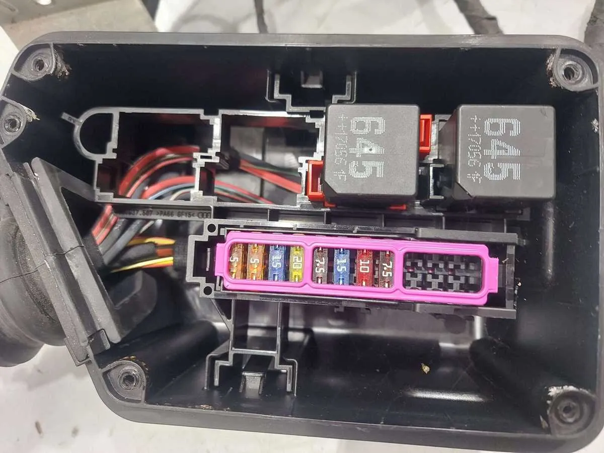
- Verify each fuse and relay placement in the main control unit to prevent system failures.
- Cross-check wiring for the battery terminals to avoid potential power shortages or overcharges.
- Use a multimeter to assess the continuity of circuits, ensuring no breaks in current flow.
Ensure that the engine control unit (ECU) wiring is properly shielded from heat and wear. Incorrect wiring in this area may lead to erratic engine behavior or poor sensor feedback.
- Always secure wire harnesses using clips and connectors rated for high temperatures.
- When replacing damaged cables, ensure they are of the correct gauge to prevent overloads.
Consult the detailed connections map when adding or modifying components like headlights, sensors, or infotainment systems. This will help in avoiding short circuits and ensure that new additions integrate seamlessly with existing setups.
- Label all wires during disassembly to facilitate easy reassembly.
- Test each wire connection with a voltmeter before reconnecting the battery.
For advanced work, consider isolating the power supply using a dedicated battery isolator switch. This is particularly useful when working on high-performance electrical systems to avoid accidental shorts.
Understanding the Main Electrical Systems in a Supercar

When diagnosing or working on the electrical components of a high-performance vehicle, it’s crucial to have a clear understanding of its core electrical systems. Focus on the power distribution, the ECU, and the communication networks. These systems are interconnected and support the optimal functioning of various electronic components.
The power distribution system, responsible for ensuring each component receives the required voltage, includes the main fuse box and relays. It handles the power routing from the battery to critical parts like sensors, actuators, and onboard electronics. Check the fuses for continuity and ensure all relays function as intended to prevent power loss to essential systems.
Next, focus on the ECU (Engine Control Unit), the brain of the vehicle. It coordinates the engine’s performance by controlling fuel injection, ignition timing, and throttle response. When troubleshooting, ensure the ECU is properly communicating with other onboard controllers and sensors. A malfunctioning ECU can lead to poor engine performance, reduced fuel efficiency, or even complete engine failure.
The communication networks in the car are typically built on CAN (Controller Area Network) and LIN (Local Interconnect Network) protocols. These networks allow seamless data transmission between the various modules, such as the transmission control unit, airbag system, and ABS. Faulty wiring or broken connections within these networks can lead to loss of communication between key systems, often causing multiple dashboard warning lights to illuminate simultaneously.
Lastly, the ground connections must not be overlooked. Ensure all ground points are clean and tightly connected. A poor ground connection can lead to erratic behavior in sensors or intermittent faults in various electronic components. Regularly inspect and clean these connections to avoid unnecessary electrical issues.
How to Read and Interpret Electrical Schematics
Start by identifying the power source and grounding points on the schematic. These are typically represented by symbols for the battery and the vehicle chassis. Ensure you understand the flow of current from the power source to various components.
Look for the symbols used to represent components like fuses, relays, sensors, and switches. These symbols are standardized, so familiarize yourself with the key provided in the diagram. Each component’s symbol will be accompanied by numbers or labels, indicating their specific function and placement.
Connections are usually drawn as lines between components, and they may include additional information such as wire colors or resistance values. Pay close attention to the color codes as they indicate specific circuits or groupings. For example, red often indicates positive voltage, while black is used for ground connections.
Pinout diagrams are crucial for interpreting connectors. Each connector has a pinout map that shows which terminal corresponds to a specific wire or component. Verify that the wire connections match the pinout map to avoid incorrect installations.
For troubleshooting, always check the flow of current, ensuring that all components receive power as indicated. If any component shows abnormal resistance or power loss, it might signal a fault in the circuit.
Remember to cross-reference components with the service manual for more details on wiring specifications, including pin configurations, voltages, and troubleshooting procedures. This will help ensure that each connection is correctly identified and interpreted.
Troubleshooting Common Electrical Issues with Supercar Circuitry

If the vehicle experiences intermittent power loss or malfunctioning components, start by inspecting the fuse box. A blown fuse can easily disrupt power flow to critical systems such as the lights or infotainment. Replacing a faulty fuse should be the first step before diving into more complex diagnoses.
Next, check the ground connections. Loose or corroded ground wires often cause erratic behavior in electronics. Ensure that the battery ground and other key grounding points are clean, tight, and free from rust. Any sign of corrosion may result in voltage drops, affecting performance.
For issues with inconsistent starting or power drain, the battery itself should be tested. Use a multimeter to check the voltage level; anything below 12.4 volts could signal that the battery is failing. If voltage drops significantly under load, it may need replacement or recharging.
If the central display or instrument cluster is malfunctioning, examine the signal connections for any signs of wear or loose pins. A poor connection in the data link can lead to inaccurate readings or complete loss of display functionality.
For persistent issues with electronic sensors or actuators, a thorough scan of the vehicle’s ECU for error codes is recommended. These codes can pinpoint issues related to faulty circuits or signal disruptions that are not immediately visible. Pay close attention to any voltage irregularities or communication errors between modules.
In case of intermittent sensor failures, inspect the related wiring harness for cracks or fraying. These issues typically occur in high-flex areas like the engine bay, where movement and heat can degrade insulation over time. Replace damaged sections of the wiring to restore proper function.
Finally, if the car has been exposed to moisture, check all connectors for signs of water ingress. Even a small amount of moisture can lead to short circuits or corrosion, which may compromise critical electrical systems. Sealing or replacing compromised connectors will help prevent future issues.