If you’re looking to install or troubleshoot your home heating and cooling system, understanding the correct way to connect the control panel is essential. Start by verifying the connections for the power, heat, cool, and common terminals. These terminals are fundamental for the proper functioning of the entire setup, and incorrect wiring can lead to operational issues or complete system failure.
Begin with the power line, typically indicated by the “R” terminal. This wire provides power to your system. Make sure it’s securely connected to the corresponding terminal on your controller. If you’re using a multi-zone setup, ensure each zone’s power wire is properly allocated.
The cooling circuit is equally important and is usually attached to the “Y” terminal. This connection activates the air conditioning system when cooling is required. It’s critical that this wire is connected correctly to avoid malfunction when switching between heating and cooling modes.
Lastly, always double-check the ground wire for safety. It should be attached to the designated terminal to ensure the system is safely grounded. Neglecting this step can lead to electrical hazards.
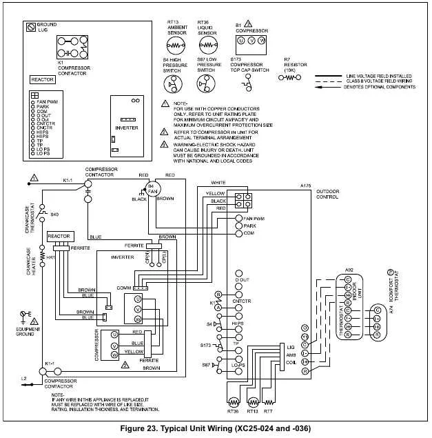
Wiring Setup for HVAC Control Unit

Ensure that the connection terminals are clearly marked for each wire. Red (R) should be linked to the power supply, while the green wire (G) connects to the fan relay. The white wire (W) activates the heating mechanism, and the yellow (Y) wire controls the cooling function. Always verify that the common (C) wire is connected to the circuit’s ground for stable operation.
If you are replacing an existing unit, take note of any color coding differences and follow the manufacturer’s guide for your specific model. For systems that require a 24V AC signal, ensure that the transformer is wired properly to supply consistent voltage to the unit for efficient performance.
To avoid malfunction, double-check that the wires are securely attached and there is no chance of short-circuiting. It’s crucial to use the correct gauge wire, as specified in the user manual, to maintain safe and optimal system functioning.
For advanced configurations, such as heat pump systems, be sure to connect the reversing valve wire (usually labeled as O or B) correctly. If your system includes auxiliary heating, ensure the appropriate terminals for emergency heat are wired accordingly.
When in doubt, always consult a professional technician to confirm that the installation meets safety standards and manufacturer requirements.
Identifying Terminals and Their Functions in HVAC Control Panels

For proper installation and troubleshooting, understanding the terminals on an HVAC control panel is essential. Below is a guide to help you recognize and identify each terminal’s function. Make sure to follow this when wiring your system for accurate control and performance.
| Terminal | Function |
|---|---|
| R | Power input for the heating and cooling system. Connect to the 24V power source. |
| C | Common terminal, which provides the return path for power from the control board to the system. |
| W | Heats the system when engaged. This terminal connects to the heating control circuit. |
| Y | Activates cooling by connecting to the cooling control system (such as the air conditioning unit). |
| G | Controls the fan. This terminal connects to the fan relay to power the fan for circulation. |
| O/B | Switches between heating and cooling modes in heat pump systems. The O terminal typically controls cooling, while B manages heating. |
| Aux | Used for auxiliary heating in heat pump systems. Engages when primary heating isn’t sufficient. |
| E | Emergency heat terminal. Used in systems with backup heating for extreme temperatures. |
Ensure each wire is connected to the appropriate terminal to avoid operational issues. Incorrect wiring may result in malfunctioning or failure of the system components.
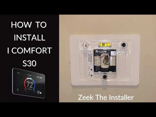
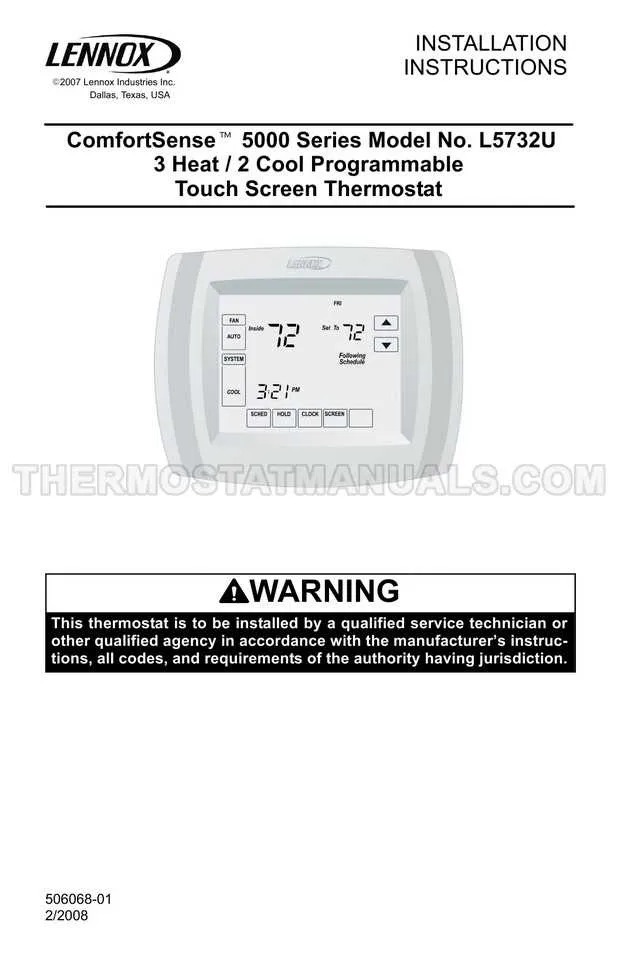
Step-by-Step Guide to Wiring a Lennox Thermostat Model

Follow these steps to correctly set up your new climate control unit:
- Turn Off Power: Ensure all power to the heating and cooling system is turned off before beginning installation.
- Remove the Old Unit: Unscrew the cover plate and detach the existing control device. Take note of the terminal connections for each wire.
- Identify Terminal Labels: Carefully check the new unit for terminal labels. Common labels include “R,” “C,” “Y,” “W,” and “G,” which correspond to specific functions such as heating, cooling, or fan operation.
- Connect the Wires: Match each wire to the terminal label. Common wire colors and their corresponding functions are:
- Red (R): Power from the system’s transformer.
- White (W): Heat signal.
- Yellow (Y): Cooling signal.
- Green (G): Fan control.
- Blue or Black (C): Common wire, completing the circuit.
- Ensure Secure Connections: Strip approximately 1/2 inch of insulation from each wire and securely connect them to their respective terminals. Tighten the screws or terminals to avoid any loose connections.
- Attach the Unit: Once all wires are securely in place, mount the unit on the wall, ensuring it is level and firmly attached.
- Power On the System: Turn the power back on and test the system by adjusting the settings on your control panel. Ensure that the heating, cooling, and fan functions operate correctly.
- Final Check: If everything is functioning correctly, replace the cover plate and ensure all settings are as per your desired preferences.
By following these steps, you can easily install and configure your climate control unit to provide efficient temperature regulation in your home.
Common Electrical Issues and Troubleshooting Tips
Ensure all connections are securely fastened to avoid intermittent issues with temperature control. Loose terminals can result in unresponsiveness or incorrect readings, especially in systems with multi-wire setups.
If your system isn’t powering on, check the circuit breaker or fuse. A blown fuse can prevent the control panel from activating. Replace the fuse if necessary, but always ensure the power is completely off before inspecting internal components.
Verify that the control wire is connected properly to the designated terminal. Sometimes, incorrect connections cause the system to malfunction, leading to heating or cooling irregularities.
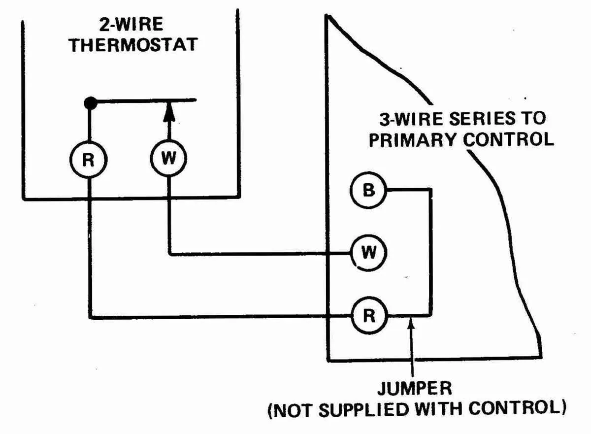
If the system is running continuously, it might be due to a faulty relay or misconfiguration of the control signals. Double-check that the jumper wires are placed correctly and that no short circuits are present within the unit.
Another issue could be poor contact with the ground. A ground loop can interfere with signals, so inspect the grounding connections to ensure proper continuity and function.
For models with advanced features, software or firmware issues may require a reset. Follow the manufacturer’s instructions to reset the unit to factory settings if troubleshooting with physical components does not resolve the problem.
Keep an eye on the wiring insulation. Damaged or worn-out insulation can lead to electrical shorts, causing system failure or erratic behavior. Replace any frayed or broken cables immediately to prevent further damage.