If you need to troubleshoot or rewire the electrical components of a 48V electric vehicle, it’s crucial to first understand the core connections and their functions. Start by identifying the battery pack, ensuring all terminals are clean and securely fastened to avoid voltage drops or short circuits. Properly routing cables will prevent overheating and ensure maximum performance.
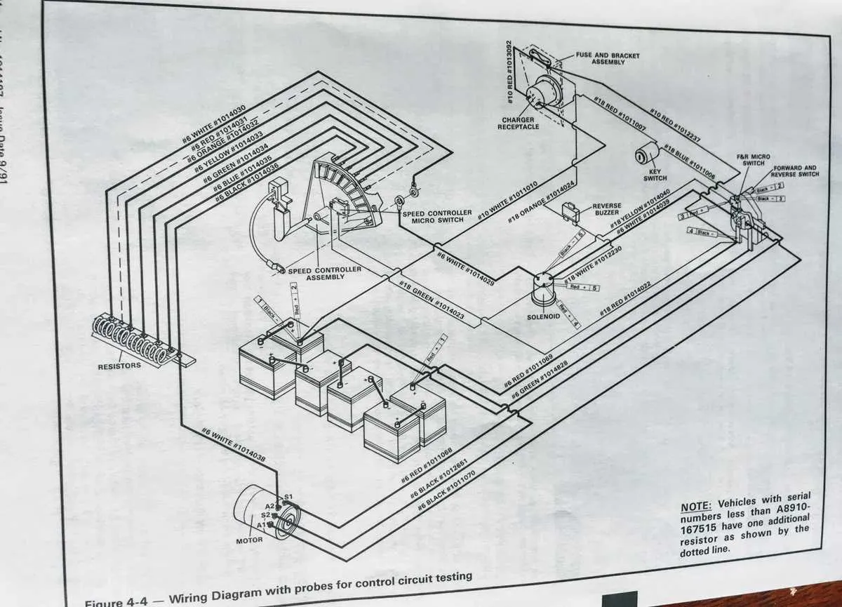
Examine the motor’s connection to the control unit; this is where most issues arise due to faulty resistors or burnt-out relays. Check the continuity of all relevant cables to the switches and brake sensors, as they can affect the overall functionality.
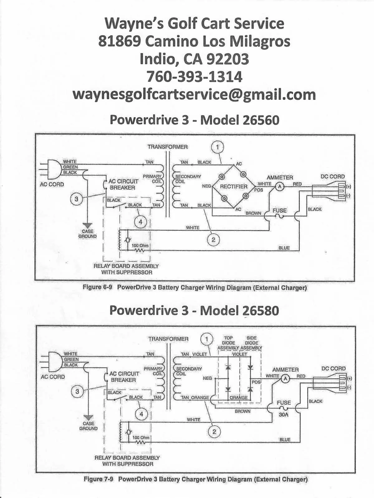
For the charging system, verify that the charger is correctly wired to the vehicle’s onboard circuitry. An incorrect hookup can lead to charging failures or even damage to the battery cells, rendering the vehicle inoperable.
When working with a 48V system, always double-check the polarity before making any connections. A reversed wire can cause immediate damage to sensitive electronic components, so extra caution is needed in this area.
Tip: Use a multimeter to ensure proper voltage levels at key points in the electrical system, especially at the motor and battery pack terminals. Regular maintenance of these components will prolong the life of your electric vehicle.
Electrical System for 48V Golf Cart

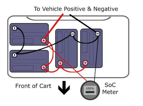
To ensure proper operation of the 48V electric vehicle, follow these key steps for setup and troubleshooting. Check the battery pack connections first. Properly connect the six 8-volt batteries in series, ensuring correct polarity. Start by attaching the positive terminal of the first battery to the controller’s input. Then link the negative terminal of the last battery to the chassis ground.
Verify the controller’s wiring for secure and clean connections. Any loose or corroded terminals can lead to system failures. The key switch should be connected to the controller’s power input, ensuring smooth activation when the ignition is turned on. Test the accelerator wiring for continuity and ensure it communicates properly with the controller.
| Component | Connection | Notes |
|---|---|---|
| Battery Pack | Series, Positive to Controller | Ensure correct polarity and clean connections |
| Controller | Input from Battery Pack | Check for loose terminals |
| Key Switch | To Controller Power Input | Test for proper activation |
| Accelerator | To Controller | Ensure smooth electrical signal transfer |
| Chassis Ground | Battery Pack Negative | Ensure solid ground for complete circuit |
For troubleshooting, if the vehicle doesn’t power on, check each component’s voltage with a multimeter. If the readings are low or inconsistent, inspect connections for corrosion. Replace any worn wires immediately. A poor ground connection can cause intermittent operation, so always check the chassis ground for solid contact.
Identifying Key Components in a 48V Electrical Schematic
Power Source: The main battery pack, typically consisting of six 8-volt cells or four 12-volt batteries, serves as the core energy provider. It is crucial to correctly identify the positive and negative terminals to avoid circuit damage.
Motor Controller: This device regulates power flow to the electric motor. It is connected directly to the battery terminals and should be checked for any signs of overheating or malfunctioning connections. Ensure that the controller is properly grounded to prevent electrical failure.
Solenoid: The solenoid acts as a switch that controls the flow of current to the motor. This component is often located between the battery pack and the motor controller. Inspect the solenoid for signs of corrosion, which can impede proper function.
Throttle Sensor: The throttle sensor adjusts the speed by monitoring the acceleration input. Typically a potentiometer, this device interacts with the controller to regulate speed. Test the sensor for proper resistance values to ensure accurate readings.
Fuses and Circuit Breakers: These safety components protect the system from electrical surges. Ensure that all fuses are rated for the appropriate amperage and check for blown fuses if power issues arise.
Grounding: Proper grounding of the system is vital for avoiding electrical shocks and system malfunctions. All components should be grounded correctly to ensure safe operation.
Key Switch: The ignition switch allows power to flow to the system when turned on. It is a simple yet critical component that should be checked for any wear or electrical faults.
Battery Chargers: The charger is connected to the battery terminals and is essential for recharging. Verify that the charger is properly connected and that it supplies the correct output voltage to ensure efficient charging cycles.
Step-by-Step Guide to Troubleshooting Electrical Issues Using the Diagram
1. Verify the Power Source: Ensure that the main power supply is functioning properly. Check the battery connections for corrosion or loose terminals. If the voltage is low, charge the batteries and retest the system.
2. Identify the Key Components: Locate the motor, controller, and switches in the circuit. Cross-reference these components with the electrical schematic to understand their connections and layout.
3. Check for Continuity: Use a multimeter to check the continuity of wires and connections. Identify any broken circuits or faulty connections that may cause power loss.
4. Inspect the Switches and Relays: Test each switch and relay for proper function. If a switch is stuck or a relay is not activating, replace or clean the components as necessary.
5. Test the Motor: If the motor is not functioning, disconnect it and test directly with the power source. A malfunctioning motor may require rewiring or replacement of internal components.
6. Examine the Controller: Check the controller for error codes or signs of overheating. If the controller isn’t functioning, ensure the connections are secure and there is no visible damage.
7. Look for Shorts or Grounds: Inspect the entire system for any shorts or grounding issues. A grounded connection could disrupt the entire electrical flow, causing malfunctions.
8. Replace Faulty Parts: Based on the diagnostic results, replace any damaged or malfunctioning components, including wires, connectors, or circuit boards. Follow the schematic to ensure correct placement and connections.
9. Retest the System: After replacing faulty parts, reconnect the system and test the unit thoroughly. Check each component’s functionality to ensure that everything is operating as expected.
How to Properly Rewire and Replace Faulty Parts in a 48 Volt Electric Vehicle

Start by disconnecting the battery to avoid short circuits or injury. Ensure the power is completely off before handling any components.
Next, inspect the motor and controller for visible damage or wear. A malfunctioning controller may exhibit symptoms like erratic acceleration or no movement at all.
- Check all terminals for corrosion or loose connections. Corroded or improperly connected terminals can cause power loss or inconsistent performance.
- Inspect the main fuse for continuity. If the fuse is blown, replace it with one of the correct rating, typically 50 amps.
Now, examine the wiring leading to the battery pack and motor. Look for fraying, cuts, or burns that could indicate shorts. Use a multimeter to verify continuity along each wire and confirm no breaks exist.
- Replace any damaged wires with high-quality, gauge-appropriate replacements. Typically, 6 AWG wire is suitable for this setup.
- Ensure that wire connections are tightly secured to prevent future issues. Soldering connections rather than relying solely on crimp connectors will improve durability.
When replacing the motor, ensure it is compatible with the existing power system. Motors should be chosen based on the vehicle’s load and use case, with an appropriate power rating for efficient operation.
For optimal performance, always check the battery pack. Replace any faulty or weak cells to ensure consistent power output. When replacing batteries, use high-quality deep-cycle units designed specifically for electric vehicles.
Finally, test the system by turning the power back on and running a short test cycle. Monitor the vehicle’s behavior, and check that all components are functioning smoothly without overheating or malfunctioning.