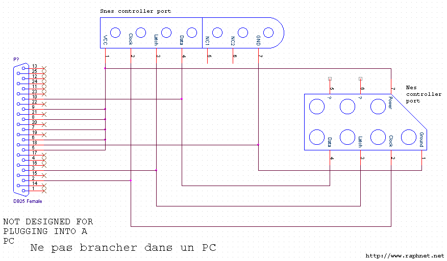
My first idea was to read the NES controller presses with Arduino and don’t connect any of the NES wires adjacent to a communication pin.
This is a schematic of how the NES controller looks on the inside. see the IC in plain sight along with the wires connecting to the cable.
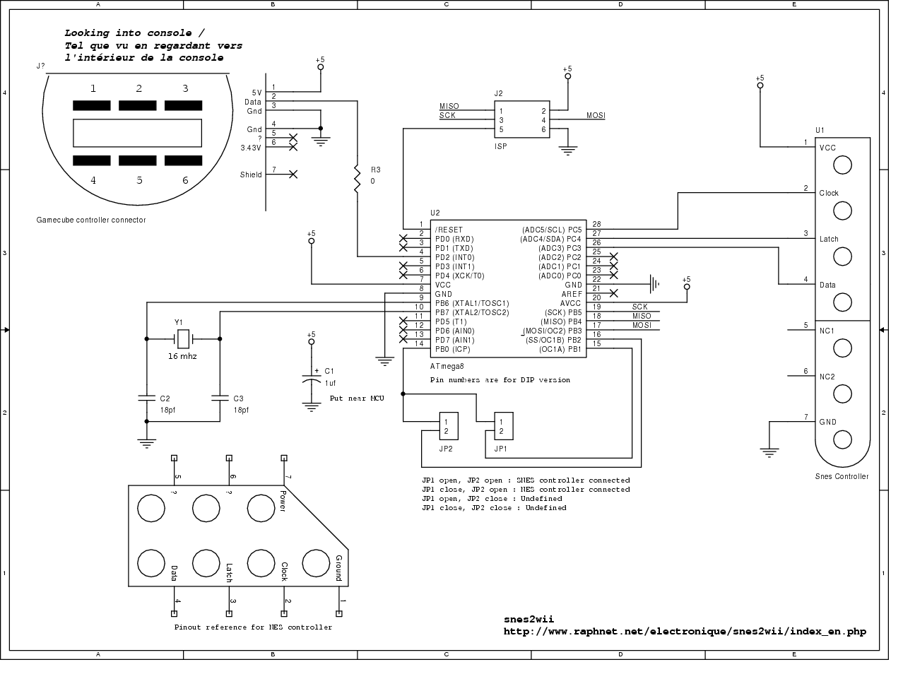
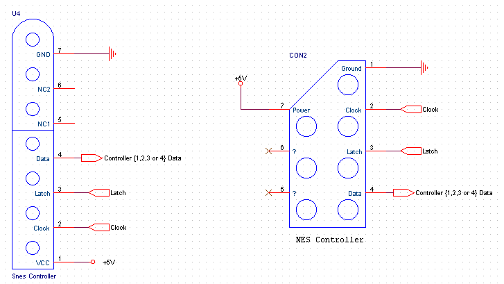
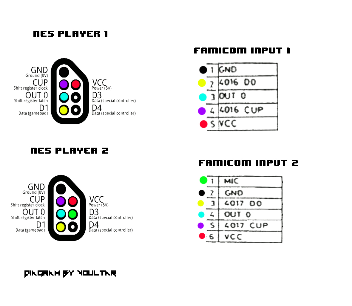
Pinout of Nintendo NES and SNES joystick controller and layout of 7 pin SNES special female connectorincluding adaptation of joystick to a. The Controller Handler interprets signals coming from the Nintendo the piece connecting the wires from the connector to the main NES circuit board. Make a USB NES Controller: This tutorial combines an original NES controller, Once you’ve connected all the wires, connect the controller to a computer and.To anyone building one of these, I found an easier method to the wiring process.
I wired the momentary pushbuttons to the controller as normal, however instead of cutting and re-wiring the cord coming out of the controller to the nes, I left that cord intact and mounted the plug to the back of the coffee table. When removing the power module, your first instinct may be to desolder all of the connections on the bottom-side of the NES PCB and withdraw the module, signal pins and all.
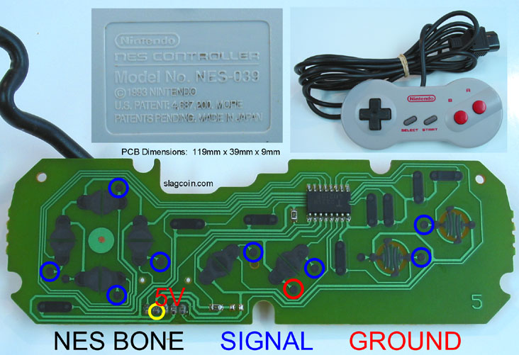
The problem with removing the 5 pins along with the modulator is that the PCB traces leading to the pins are only present on the top-side of the NES PCB. This code uses an old-school ‘s NES controller to control a servo and an LED with the Arduino.
With this code, the ‘up’ pad turns a servo to degrees, ‘right’ turns it to 90, and ‘down’ turns it to 0 degrees. Hacking into an old NES controller::Update >> I wrote this stuff a long time ago and now it may sound really stupid.
First up, the very first Nintendo Entertainment System (NES) controller, in all its boxy glory. It’s pretty simple: 8 buttons, 1 shift register, a simple PCB, and a simple injection molded plastic housing.Nintendo NES and SNES joystick controller pinout diagram @ schematron.orgUntitled Document
