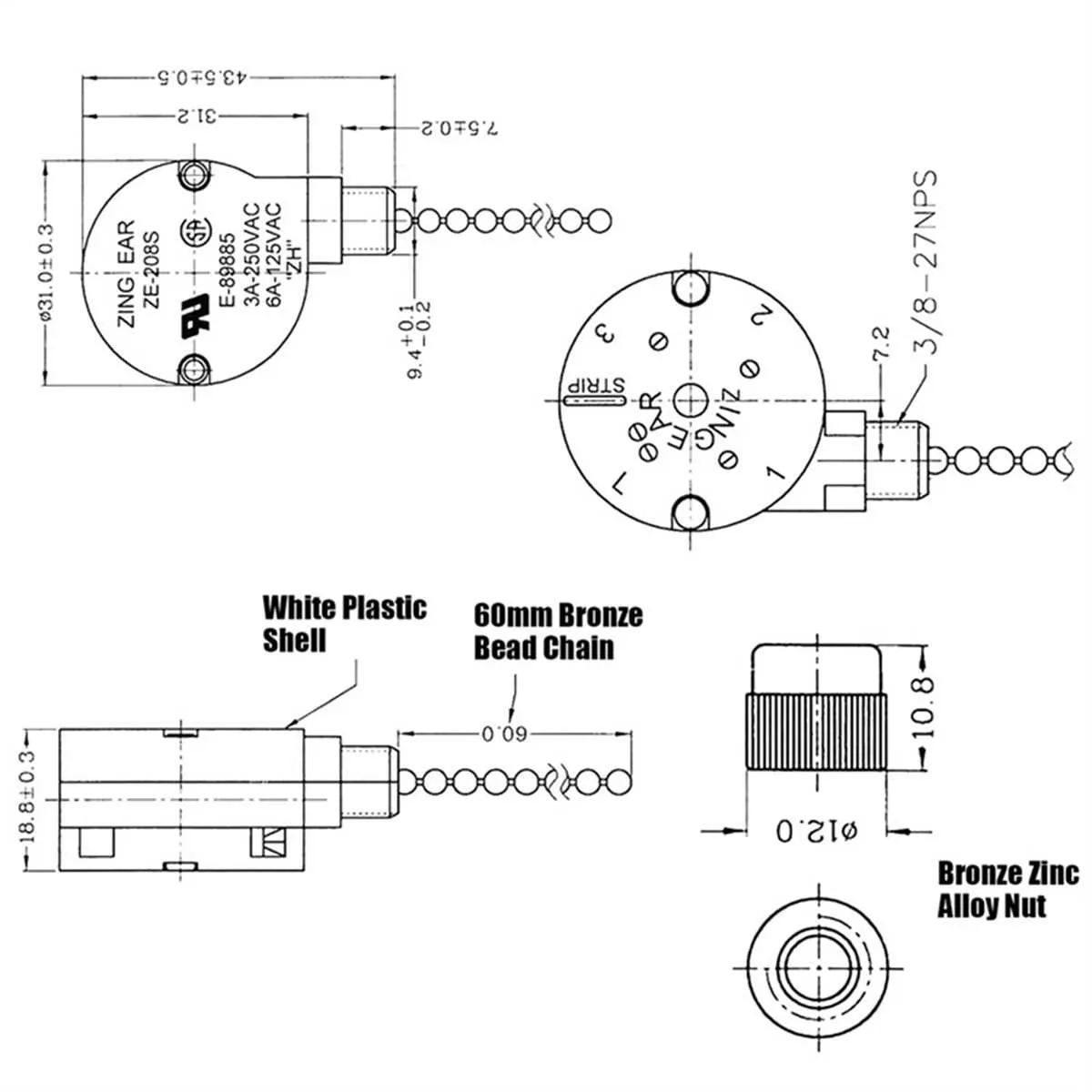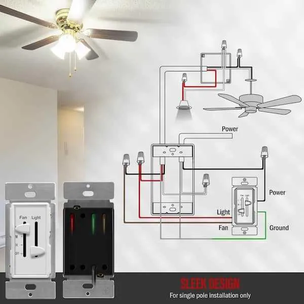
To successfully install an overhead circulator with three variable airflow levels, ensure you understand the wiring process. Begin by identifying the power source and the necessary components: a switch with multiple settings, a junction box, and the corresponding wires. The most common setup will involve connecting the live wire to the switch, which regulates the airflow intensity. From there, each setting will control a different connection, allowing for seamless transitions between low, medium, and high speeds.
Pay attention to wire color coding to avoid confusion during the installation. The typical color scheme includes black (live), white (neutral), and green (ground), but it may vary depending on the manufacturer. If you’re dealing with an older model or a system that uses a different color standard, double-check the product manual for confirmation. Incorrect connections can lead to malfunctions or safety hazards.
Once the system is properly wired, test each setting to ensure the air circulator operates smoothly. If one of the levels doesn’t work, recheck the connections at the switch and the unit itself. Verify that the wires are tightly secured and that there are no exposed copper strands that could cause a short circuit.
Professional installation is recommended if you lack experience working with electrical systems, as improper wiring can lead to both equipment failure and safety risks. If you choose to proceed independently, take all necessary precautions and consider using a multimeter to confirm proper electrical flow at each stage.
Three-Level Control for Electric Air Circulation Unit

For a proper connection of an electric air circulator with three adjustable rotation levels, follow these detailed steps. First, ensure that the unit is powered off. Identify the common terminal, usually marked as “C” or “COM,” which connects to the power source. The wire for this terminal should lead to the switchboard where the incoming power is connected.
Next, connect the wires for each rotational level to their respective terminals. Typically, each level is marked as “L1,” “L2,” and “L3.” These correspond to the different speed settings: low, medium, and high. The wire for the low setting usually connects to “L1,” the medium to “L2,” and the high to “L3.” Ensure that these are securely connected and insulated to prevent short circuits.
For controlling the direction of airflow, if your unit has reverse functionality, it will be managed through a separate connection or a toggle on the same control switch. Double-check that all connections are firmly tightened to avoid any loose wiring issues.
Lastly, ensure that all ground wires are properly attached to the unit’s metal housing to avoid electrical hazards. Once the connections are complete, switch on the power and test the unit at all rotation settings to ensure proper operation and secure wiring.
Understanding the Components of a 3-Speed Ceiling Fan Wiring
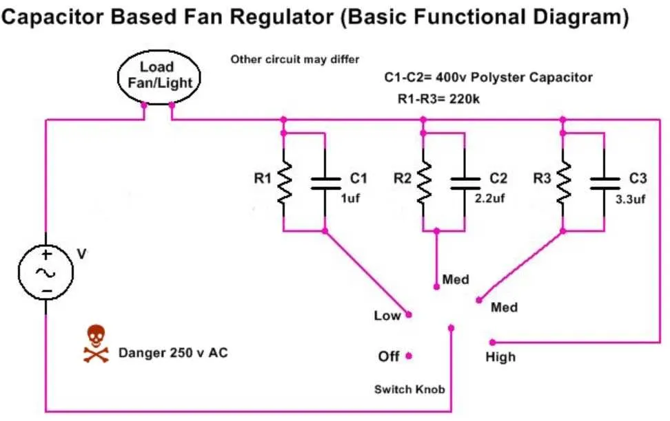
To install or troubleshoot a multi-setting device, it’s essential to understand the role of each component in the electrical setup. A typical 3-level unit includes a motor, capacitor, and switch. These elements work in unison to control the rotational force and power output to the unit, allowing for different operational intensities.
Motor: The motor is the core element, converting electrical energy into mechanical movement. Depending on the desired setting, the motor will rotate at different rates. It is important to ensure that the motor is capable of handling varying loads without overheating.
Capacitor: The capacitor plays a crucial role in adjusting the current flow and determining the unit’s operational strength. It stores electrical charge and releases it to modify the motor’s power input, allowing for precise control over rotation speed. A malfunctioning capacitor can lead to irregular performance or failure to start.
Switch: The switch controls the power distribution to the motor and adjusts the intensity of the current flowing through it. It works by altering the resistance within the circuit to achieve different operational levels. If the switch is not functioning properly, it may cause inconsistent behavior or prevent the unit from working altogether.
Wiring Connections: Proper wiring is key to ensuring safe and effective operation. Incorrect connections can lead to electrical shorts or system failure. Always double-check that connections match the manufacturer’s guidelines to avoid potential issues.
Make sure each component is in good condition and properly installed to maintain the reliability and performance of the entire system.
Step-by-Step Guide to Installing a 3-Speed Air Circulation Device
Start by disconnecting the power from the main electrical source. Ensure that the circuit breaker is off to avoid any risk of electric shock.
Next, identify the incoming wires: typically, there are three–black (hot), white (neutral), and green or copper (ground). These wires need to be correctly connected to the device’s corresponding terminals.
For the control system, use a switch that allows multiple adjustments. You will need to connect the black wire from the power supply to the input terminal of the switch. Then, attach the output terminal of the switch to the corresponding wire leading to the motor. The white wire should be connected directly to the motor’s neutral terminal.
The ground wire must be attached to the metal frame or a dedicated ground terminal for safety. This will prevent any electrical fault from causing harm to the system or individuals in the vicinity.
If your system includes a pull chain, connect it according to the manufacturer’s instructions, ensuring it interacts correctly with the power settings.
Once all connections are made, secure the assembly in place using the mounting brackets. Ensure all screws and bolts are tightly fastened to avoid any movement during operation.
Double-check all connections before restoring power. Test the functionality to ensure each adjustment works as expected, and verify there are no unusual sounds or vibrations.
Important: If you’re unfamiliar with electrical installations, consider consulting a licensed electrician to prevent errors or hazards during the setup process.
Common Wiring Mistakes to Avoid When Installing a 3-Speed Ceiling Fan

Ensure correct installation by following these key tips to prevent common errors:
- Double-check the power supply. Always turn off the circuit breaker before starting work to avoid electrical shock or short-circuiting.
- Correctly identify the three control terminals on the motor. Misconnecting wires to the wrong terminals can lead to malfunction or even damage the unit.
- Ensure you use the appropriate wire gauge. Using too thin a wire for high voltage can result in overheating and potential hazards.
- Do not bypass the switch box. Some individuals attempt to directly connect the motor to the power source, which can cause improper functioning.
- Verify the neutral wire connection. It’s essential that the neutral wire from the motor is correctly tied to the neutral power wire to ensure proper operation.
- Never leave exposed wires. Proper insulation of each wire connection prevents accidental contact, reducing fire risks and improving safety.
- Double-check for any loose connections. A poor connection can lead to unreliable operation or complete failure of the unit.
Taking care to avoid these pitfalls will ensure smooth and safe operation once the installation is complete.