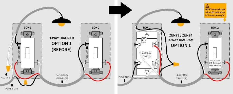
For a reliable connection setup, always ensure that the central terminal is connected to the common point of your device or system. From here, configure the first terminal to connect to the supply voltage, while the second terminal should be wired to the output that requires activation.
When configuring a system with multiple states, it’s important to understand how the middle position should function. This will allow you to determine the correct positions for both the positive and negative power sources, ensuring each state transitions smoothly without interference.
In this configuration, be cautious of short circuits or incorrect placements of wires that could cause the device to malfunction. Properly isolate the connections to prevent any accidental crossings between lines. Additionally, it’s highly recommended to use color-coded wires for easy identification during maintenance.
Ensure the device’s terminals are properly aligned with your power system’s requirements to avoid power overloads or issues with voltage flow. Testing each configuration before final installation will also help in verifying its efficiency and reliability.
When creating such a setup, consider using materials with higher resistance to wear and tear, ensuring longevity and stability of the connections. This is especially important in high-voltage applications or systems requiring frequent switching.
Wiring an ON-OFF-ON Mechanism
For a mechanism with three positions, where each state controls a different circuit, connect the central terminal to the power source. The two outer terminals should each be linked to distinct load paths. The center terminal acts as the common reference, while the outer terminals provide alternate connections based on the desired position. To manage the flow of current, ensure the correct orientation of the component inside the assembly, which should connect the power source to one of the two outer terminals when switched.
When setting up, it’s critical to identify which position corresponds to each load configuration. For the first position, connect the appropriate load to one of the outer terminals, and do the same for the second position using the opposite outer terminal. A reliable mechanism will ensure a clear, stable transition between different circuits based on the user’s input, directing the current flow to either connected load as needed.
Understanding the Pinout Configuration of an On Off On Toggle Switch

To effectively use an On Off On device, you must recognize its terminal layout. Typically, this type of component features three terminals: one common terminal and two additional terminals for each position of the mechanism. The common terminal (often called the center pin) connects to the load or power source, while the other two terminals correspond to different output states depending on the toggle’s current position.
When configuring, it’s important to identify the common terminal to ensure proper connection. The other terminals correspond to either the positive or negative line of the circuit, depending on the toggle’s position. This configuration allows for seamless switching between two distinct connections, making the device versatile for applications requiring multiple states.
For correct functionality, ensure that the device’s common terminal is wired to the central power source or load, while the remaining terminals are connected based on the desired output states. Miswiring can result in malfunction or improper switching behavior.
How to Wire an On Off On Toggle Switch for Basic Applications
To set up a basic circuit with an on-off-on mechanism, follow these steps:
- Identify the Terminals: There are typically three terminals–one for input and two for output connections. The center terminal serves as the common point, while the other two terminals handle the switching between two outputs.
- Connect the Input Wire: Attach your input wire to the central terminal. This wire will carry the power or signal into the system.
- Wire the First Output: Connect one of the side terminals to the first output device. This is the active terminal when the mechanism is in one of the two positions.
- Wire the Second Output: Similarly, connect the second side terminal to the second output. This terminal will be active when the mechanism is in the opposite position.
- Secure Grounding (if necessary): In some applications, grounding is required. Ensure that the common or ground wire is properly connected to the relevant part of your circuit, often to the common terminal.
Ensure all connections are secure before testing the system. This setup allows for the switching between two circuits or outputs based on the mechanism’s position, providing flexibility for various basic applications.
Advanced Techniques for Circuit Control in Design
To optimize control in your circuits, consider using a 3-position control mechanism with a dual-state operation. When connecting such a component, always ensure the middle terminal is routed to the primary functional element, such as the microcontroller or relay, to establish a clear neutral position.
Ensure proper isolation for each contact in the device to avoid unintended shorts when transitioning between positions. Use diodes for protection against potential backfeed when multiple paths share the same current source.
For improved response times, implement low-resistance contacts in critical positions, ensuring that signal integrity is maintained across the range of operation. Adding capacitors across terminals can help smooth transitions and minimize signal noise.
Another technique involves using magnetic components to enhance the stability of the system, especially in environments with high electromagnetic interference. These elements can prevent accidental switching or signal degradation.
Consider integrating a feedback loop to monitor each position and adjust the control parameters dynamically, ensuring the system responds to changes without delays.