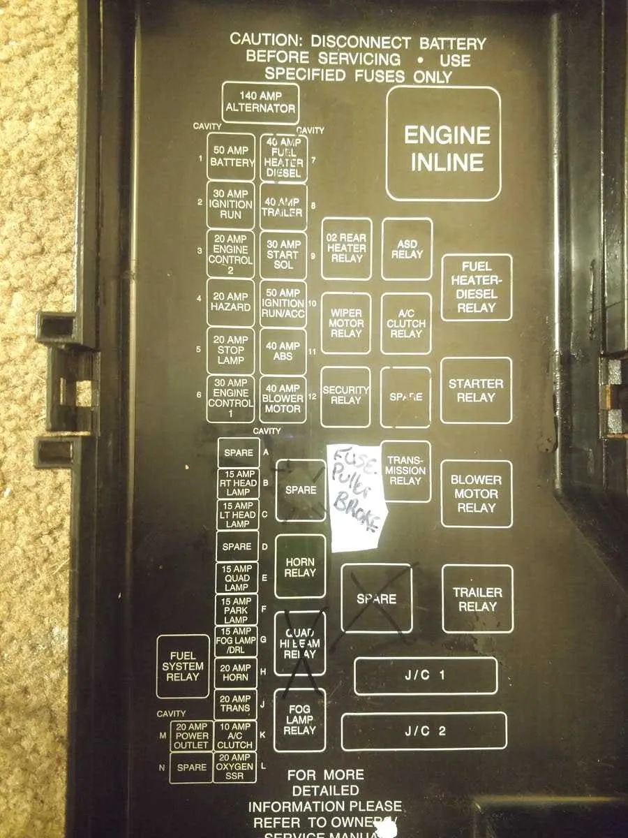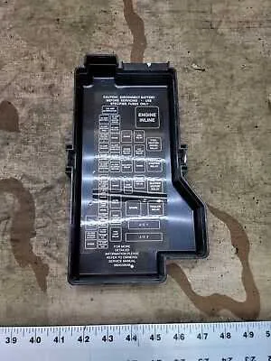
If you’re experiencing electrical issues with your 2001 pickup truck, understanding the arrangement of its power distribution components can save you time. The central unit responsible for managing electrical circuits is located under the dashboard and near the engine compartment. Referencing the system’s schematic will help pinpoint the location of specific relays and connections that may need maintenance.
For a quick fix, begin by inspecting the main relay panel located on the driver’s side. This section houses multiple critical fuses and relay components, controlling essential features such as lights, engine start, and air conditioning. Make sure to check each fuse for any visible damage, such as corrosion or burn marks.
The secondary relay location on the engine side is designed to support the primary power needs for components such as the alternator and fuel system. Ensure that you’re using the correct amperage fuses for each circuit to avoid further electrical faults.
Keep a copy of the electrical system map nearby whenever troubleshooting these systems. It is essential to identify any faulty components by matching the exact circuit configuration with the system’s plan.
01 Truck Electrical System Layout

For efficient troubleshooting and maintenance, it’s crucial to know the exact layout of your vehicle’s electrical system components. Below is a detailed guide on key circuit areas and their functions in your 2001 truck.
- Engine Compartment Circuitry: This area houses the primary fuses related to the engine and ignition system. It includes the main relay, which controls power distribution to engine control units.
- Interior Circuitry: Located under the dashboard, this section handles various components such as the air conditioning system, interior lights, and the power seats. It’s important to know where the relays for these systems are located to avoid unnecessary disassembly.
- Battery Management: The battery is connected to the main power relay, ensuring a consistent flow of electricity throughout the vehicle. Problems here can often cause power failure issues across various modules.
- Power Distribution System: Ensure that all connections are tightly secured. Loose or corroded connections may lead to partial power failure in key systems such as braking and steering.
When troubleshooting electrical issues, always check the status of the relevant relay and ensure no faulty connections are present. Ensure proper voltage ratings to avoid system damage.
Common Problems: Often, electrical issues in vehicles are caused by a blown circuit, poor grounding, or corrosion. A systematic inspection starting from the power supply area is recommended to isolate the issue quickly.
How to Locate the Electrical Panels in a 2001 Dodge Ram
The primary electrical panel is found beneath the dashboard on the driver’s side, close to the steering column. Remove the cover by gently pulling it out to access the fuses and relays controlling interior and engine components.
The secondary panel is situated under the hood near the battery. It contains higher-amperage fuses that protect critical systems like the cooling fan, ignition, and fuel pump. Lift the plastic lid to reveal the layout of the circuits.
Refer to the inside of each panel’s cover for labeling, which identifies each fuse or relay’s function and amperage rating. For precise replacement or troubleshooting, use a test light or multimeter to verify continuity before swapping any elements.
Ensure the vehicle is off and the key is removed before handling any electrical components to prevent shorts or injury. Keeping a flashlight handy helps locate smaller units in low-light conditions.
Understanding the Layout and Its Components

Locate the power distribution center under the hood, typically near the battery or firewall, for easy access. The unit contains multiple protective elements designed to safeguard electrical circuits. Each element corresponds to a specific system such as headlights, ignition, or cooling fans.
Inside, you will find a set of cartridge-style and blade-style protectors arranged systematically. Each protector is marked with an amperage rating and a position number. Referencing the legend printed on the underside of the cover helps identify each circuit’s function quickly.
Inspect the connectors for signs of corrosion or damage, as these can cause intermittent power loss or system failures. When replacing a faulty protector, match the exact amperage to avoid overheating or wiring damage.
Several relays may also be housed within this unit, controlling high-current circuits through low-current signals. Understanding which relay corresponds to which component allows for efficient troubleshooting when a particular function stops operating.
Familiarize yourself with the layout to perform routine maintenance or emergency replacements efficiently, minimizing downtime and avoiding costly repairs.
Common Electrical Protection Issues and How to Fix Them in a 2001 Dodge Ram
Identify the specific blown element by testing with a multimeter. Start by removing the relevant protective component and visually inspecting for breaks or burn marks. Replace any damaged units with ones matching the exact amperage to avoid electrical hazards.
Corrosion often causes poor connectivity. Clean terminals and contacts using electrical contact cleaner and a small brush. Ensure connectors fit tightly to prevent intermittent power loss.
Loose connections may trigger system malfunctions. Check wiring harnesses linked to the electrical protection center for frayed or loose wires. Secure any loose connections with proper crimps or soldering and use heat shrink tubing for insulation.
Overloading circuits leads to repeated failures. Avoid adding aftermarket electrical devices without upgrading the protection system accordingly. If multiple components fail frequently, consider upgrading to a higher-capacity protective panel designed for increased load.
Resetting the control unit can solve some faults. Disconnect the vehicle’s battery for several minutes, then reconnect. This resets onboard electronics that monitor circuit integrity and can clear false fault signals.
Regular maintenance and timely replacement of worn parts prevent major electrical issues. Always consult the vehicle’s service manual to confirm correct part specifications and locations.