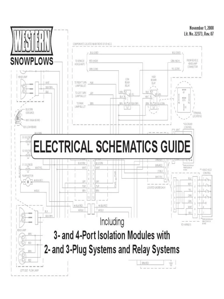
Begin by grounding the black/orange wire to the vehicle chassis using a clean, rust-free bolt near the battery. This wire is responsible for activating the motor relay and must have solid contact with bare metal.
Connect the red wire with the inline fuse directly to a key-on power source. This ensures the controller receives power only when the ignition is on, preventing battery drain.
Route the white wire to the signal terminal on the solenoid valve marked “Raise.” This line activates vertical movement and should be tested with a multimeter before permanent connection.
Attach the green line to the left-turn valve coil and the blue one to the right. These control lateral positioning and must match the correct coil; reversing them will invert the directional logic.
Ensure the isolation module connects securely between the control switch and vehicle lighting system. For setups using HB3/HB4 headlamps, use ports B and C with the appropriate adapter harness to maintain correct low/high beam switching.
Double-check that all grounds return directly to the negative battery post and not through secondary points. Intermittent faults often stem from overlooked grounding inconsistencies in older truck bodies.
Connection Layout of a Heavy-Duty Blade System
Connect the red wire from the controller directly to a fused ignition source (typically 15A) to ensure safe operation. Route the black ground lead to the negative battery terminal or a clean chassis ground. Use a relay-rated 12V power line for the motor lead–commonly orange–linked through a 250A fuse close to the battery.
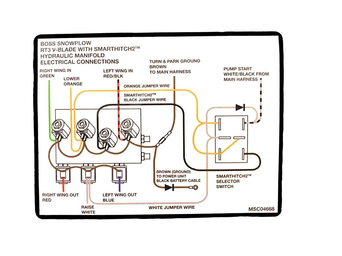
Attach the white trigger cable to the solenoid small terminal labeled “S,” not “I” or “R.” This prevents false engagement. The blue and green control wires manage the left and right hydraulic valves; ensure they match the directional switch outputs precisely. Use weatherproof connectors to avoid moisture interference.
Mount the isolation module securely under the hood, away from moving parts. Label the harness ends by function (lift, angle left/right, float) to simplify seasonal dismounting. Confirm that the harness from the vehicle grille connects snugly with the blade-side connector–usually a 9- or 12-pin plug. Clean all contacts with dielectric grease before winter operation.
Solenoid and Motor Relay Wiring Explained
Connect the positive battery terminal to the large post on the motor solenoid using a 2-gauge copper cable rated for high current. Ensure the ground connection runs directly from the motor housing to the negative battery terminal or chassis ground point with similar gauge wire.
The ignition-switched power source must feed a fused 12V signal to one of the small terminals on the solenoid. Use a 10A inline fuse and confirm voltage presence only when the key is in the ON position. The other small terminal should connect to the control switch or controller output that triggers the hydraulic motor.
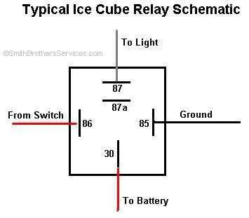
For systems using a relay instead of a continuous-duty solenoid, use a 30/40A automotive relay. Terminal 30 connects to the battery through a fused lead, terminal 87 to the motor positive post, terminal 85 to ground, and terminal 86 to the switch signal. Always verify continuity and resistance with a multimeter before final connection.
Avoid using aluminum wire or crimped connections without dielectric grease. All terminals must be crimped and soldered where possible, with heat-shrink tubing to prevent corrosion. Secure all cables with insulated clamps, away from heat sources and moving parts.
Connecting Headlight and Turn Signal Circuits
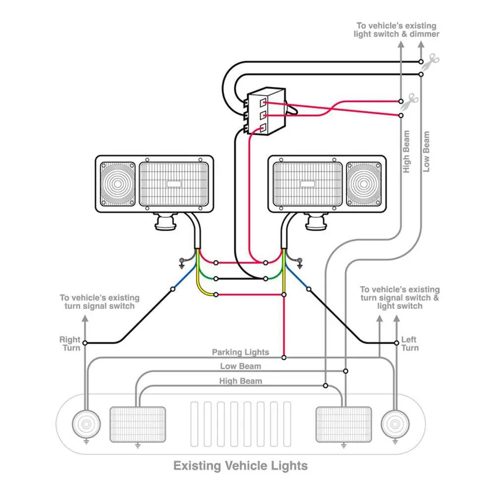
Start by identifying the vehicle’s low beam, high beam, and turn indicator wires using a multimeter. Match these to the harness input leads marked LT BLU (left turn), DK BLU (right turn), RED (high beam), and LT GRN (low beam). Do not rely on wire color alone–confirm function with voltage testing while activating each light manually.
Use Scotchlok or heat-shrink butt connectors to tap into factory circuits without cutting factory wiring. Always connect the high and low beams to their designated relays in the control module. Failure to isolate beam control will result in flickering or non-responsive lamps.
For turn signals, ensure continuity from the vehicle’s signal feed through the adapter to the auxiliary lamps. If using a DRL-equipped truck, install a diode inline on the low beam to prevent backfeeding. Confirm grounding at each lamp with a direct connection to the chassis using a star washer and dielectric grease to avoid corrosion.
Once all connections are secure, test each function–left turn, right turn, low beam, and high beam–individually. Use a fused test lead to simulate signal input if needed. Avoid shared grounds between headlamps and motors to prevent voltage drops or dimming during activation.
Isolation Module Connections for MVP and UltraMount
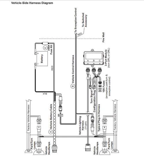
Use the 3-port isolation control module with MVP and UltraMount setups. Port 1 connects directly to the vehicle control harness. Ensure the white 10-pin plug interfaces properly with the controller harness under the dash.
- Port 1: Vehicle-side harness (control circuit). Connect the 4-pin controller and 10-pin white plug here. Route wires securely to avoid pinch points near pedals.
- Port 2: Lighting interface. Match the vehicle-specific light adapter kit to ensure correct headlamp operation. Use configuration 26400 for GM, 8436 for Ford, or 8430 for Dodge platforms.
- Port 3: Power unit interface. Attach the grill-mounted harness here. The 11-pin plug leads to the hydraulic assembly and includes the signal path for lift, angle, and float functions.
Always ground the black/orange wire from the controller to a clean chassis point. Fuse protection is critical: insert a 15A fuse between the battery feed and isolation module input. For MVP Plus units, ensure relay 56131 is seated properly inside the control module housing. If using a multiplexed headlamp system, disable DRL circuits to prevent flicker or loss of control.
Secure all harness junctions using dielectric grease and weatherproof boots. Label each plug using color codes: red/green for power, black/yellow for control. Do not splice wires unless using soldered joints and heat-shrink tubing.
To test, activate controller and verify blade motion. If unresponsive, check pin 3 of the 4-pin connector for 12V reference signal during joystick actuation.