When constructing or analyzing a lighting system, understanding the key components is crucial for effective design and functionality. The electrical connection, for instance, is one of the primary aspects to ensure proper operation. Without a stable electrical contact, the device will fail to power up, regardless of the quality of the other elements. The switch mechanism plays a pivotal role in controlling the flow of electricity and adjusting brightness.
Another significant feature is the housing, which not only supports the internal elements but also serves as a protective cover for sensitive parts like the filament or the LEDs. The reflector or light-directing structure is essential for guiding and dispersing light in the desired direction, enhancing both efficiency and aesthetic appeal.
The socket or mounting area for the light source must be secure and compatible with the chosen bulb type. Finally, the support structure, often overlooked, ensures the stability and positioning of the entire system, preventing vibrations or potential damage during operation.
Key Components of a Lighting Fixture Overview

Start by identifying the key elements essential for the functioning and design of a light source. These are the core components that enable efficient operation and ensure aesthetic appeal. Understanding each element is crucial for both maintenance and design improvement.
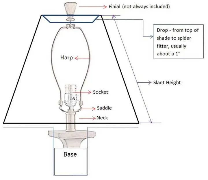
- Base: Provides structural support and houses the electrical connections. Typically made of sturdy materials to ensure stability.
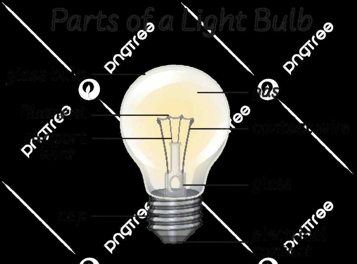
- Bulb: The energy-emitting unit, which can vary depending on the desired light output and energy efficiency. Options include incandescent, LED, and fluorescent types.
- Socket: The component that securely holds the bulb and connects it to the power source. It ensures a stable electrical connection.
- Shade: Serves to diffuse the light, reduce glare, and contribute to the overall design. Materials may include fabric, glass, or metal.
- Switch: Controls the flow of electricity to the light source. It can be a simple toggle or a more advanced dimmer.
- Wiring: The electrical connections that transfer power from the source to the bulb. Proper insulation and placement are vital for safety.
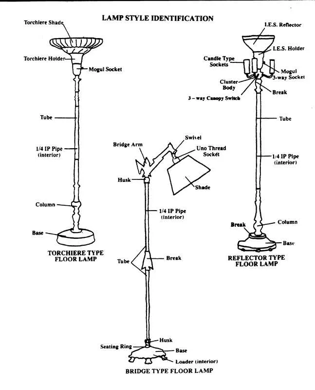
- Stand: For fixtures requiring support from the ground, the stand serves both as a design feature and a functional element for height adjustment.
Ensure that each of these components is compatible with the rest of the fixture to avoid malfunction and maximize longevity. Regular maintenance and understanding the specific role of each element will prolong the life and efficiency of the setup.
How to Identify the Power Source and Its Role in Functionality
The power source is the fundamental component that enables illumination. Typically, this is either a direct electrical connection or a battery, depending on the device’s design.
For electrical setups, locate the wires connecting the fixture to the main power supply. If the setup is battery-operated, identify the battery compartment and ensure it is correctly positioned for optimal current flow.
The power source serves as the energy provider, supplying the necessary electrical current to activate the light-emitting components, whether it’s an incandescent bulb, LED, or fluorescent tube. Proper identification and connection of the power source ensure efficient operation and prevent potential malfunctions.
| Power Source Type | Functionality | Maintenance Tip |
|---|---|---|
| AC Power (Electricity) | Delivers consistent energy, ensuring stable performance. | Regularly inspect wires for wear and tear; replace damaged connections. |
| Battery | Used in portable units for flexible use, but requires regular battery replacement. | Replace batteries before they deplete fully to maintain optimal function. |
Ensure the power source matches the requirements of the light-producing element to avoid damage or inefficiency. Improper connections or mismatched voltage ratings can result in poor performance or even failure of the device.
Understanding the Light Bulb Socket: Types and Connections

The light bulb socket plays a crucial role in establishing a secure connection between the bulb and the electrical circuit. Choosing the right socket type is essential for ensuring proper function and safety. Among the most common socket types are Edison screw (E26, E27), bayonet, and GU10.
The Edison screw socket is the most widely used, typically found in household fixtures. The socket’s metal threads engage with the bulb’s base, forming a stable electrical connection. The E26 (North America) and E27 (Europe) are the standard sizes. When wiring these, ensure the socket is properly grounded and that the electrical connections are tight to prevent arcing.
For applications requiring a more secure fitting, such as in automotive or specialized equipment, the bayonet socket is a reliable choice. These feature a pair of pins on the bulb base that slot into corresponding grooves in the socket. A simple twist locks the bulb into place, providing a secure, vibration-resistant connection.
In halogen and LED lighting, GU10 sockets are frequently used. These are designed for high-voltage applications and feature two small pins that fit into the socket. When installing, ensure the pins are aligned with the socket’s grooves to avoid damaging the connection.
Wiring connections vary by socket type, but the general principle remains consistent: connect the live wire to the center terminal, the neutral wire to the outer terminal, and always ensure the grounding terminal is properly connected when necessary. For safety, it’s essential to use the correct gauge wire for your installation and check the socket’s voltage rating against the bulb’s requirements.
Wiring Configuration: Mapping the Electrical Flow in a Lamp

Ensure a direct connection between the power source and the filament by utilizing an insulated wire for the positive lead. This wire should be connected securely to the terminal on the base. The negative terminal must link to the switch or dimmer, with the return wire running to the neutral side of the power supply. Make sure the wiring is appropriately rated for the current to prevent overheating.
Use a switch that operates on a simple on/off mechanism, or for adjustable brightness, opt for a dimmer circuit. The switch should be placed in line with the positive lead to control the flow of electricity. This setup allows you to cut off the electrical flow when the switch is in the “off” position, ensuring safety and functionality.
The grounding system must connect to the metal parts of the housing. A grounding wire, typically green or yellow, should be securely attached to a dedicated ground terminal. It’s crucial for preventing electric shock hazards and ensuring proper electrical dissipation in case of a short circuit.
If you’re using a polarized socket, make sure that the hot wire connects to the smaller prong while the neutral wire connects to the larger prong. This guarantees that the flow is directed properly through the fixture, aligning with standard electrical code requirements.
Verify the voltage rating of all components to match the intended electrical supply. Components should be rated to handle the specific current and voltage levels without risk of damage. Double-check for any potential overload issues, especially in cases of retrofit installations or when adding new electrical features.