When constructing or analyzing the layout of a hauling unit, understanding the structure and configuration is essential. The frame supports and connects all critical elements, providing stability for load distribution. The coupling mechanism is responsible for secure attachment to the towing vehicle, ensuring safe travel. Pay attention to the hitch system, as it dictates both the maneuverability and weight-bearing capacity of the entire setup.
Next, the wheels and axles are fundamental to maintaining smooth motion and supporting substantial weight. Proper alignment and maintenance of these elements are necessary for reducing wear and tear over long distances. The suspension system further aids in cushioning the unit, protecting both the cargo and the chassis during travel over uneven terrains.
The braking system must be robust, with regular checks to ensure responsive action in emergency scenarios. Additionally, the electrical and lighting systems play a crucial role in visibility and safety, particularly when traveling at night or under low-visibility conditions. Each component must be carefully maintained and properly integrated to ensure optimal performance and safety on the road.
Key Components of a Transport Vehicle Layout

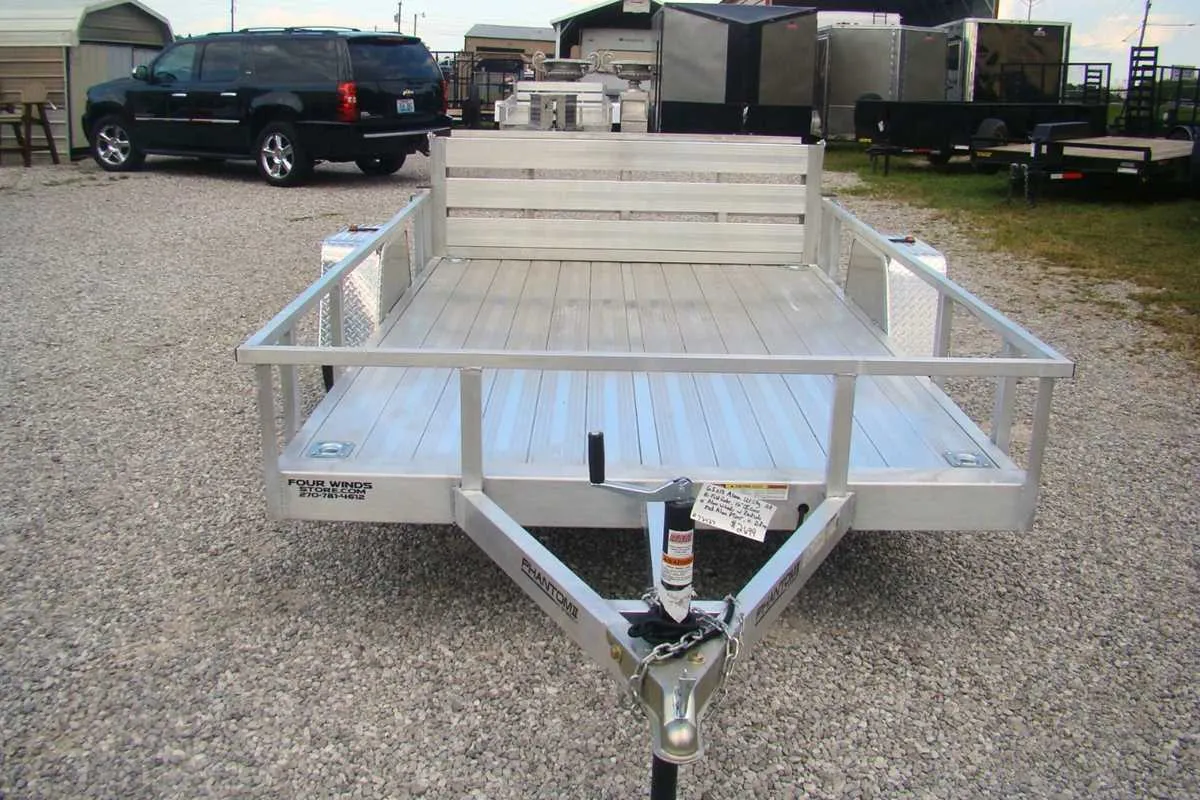
The connection mechanism, such as the hitch or coupling system, ensures secure attachment between the towing vehicle and the load-carrying unit. It typically includes a ball socket or fifth-wheel mechanism, designed to support heavy loads while enabling smooth turns.
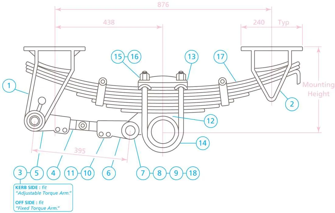
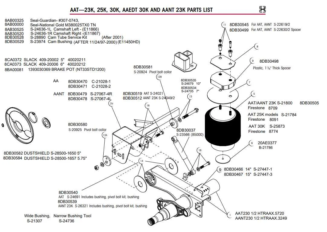
Suspension systems are crucial for absorbing shocks and maintaining stability. They include leaf springs, air bags, or torsion bars, all aimed at minimizing the impact of road irregularities on both the cargo and vehicle.
The axle assembly supports the wheels, enabling rotation and weight distribution. This system often features dual axles for enhanced stability and weight handling, with wheel hubs located at the ends of each axle to house the bearings that allow smooth wheel rotation.
Braking systems, including air or hydraulic brakes, are essential for ensuring safe stopping. Air brakes are common in larger units, offering better control over the vehicle’s momentum, while hydraulic systems are often used for lighter loads.
Lighting and signal equipment, including tail lamps, brake lights, and turn signals, are mandatory for visibility and safe operation on the road. These components also include reflectors for added visibility at night or in low-light conditions.
Loading ramps or lift gates facilitate the easy transfer of cargo. Ramps often use a gradual slope, while lift gates feature hydraulic systems that raise and lower cargo with minimal physical effort.
The chassis frame acts as the primary support structure, built from durable materials like steel or aluminum. It ensures that the vehicle maintains its shape and rigidity, supporting the weight of the load while withstanding environmental stresses.
Wheels and tires are essential for maintaining traction and stability. They are designed to handle varying loads and road conditions, with tire pressure monitoring systems ensuring that the tires remain inflated within optimal levels for safety and performance.
Rear bumpers and side panels offer protection to the vehicle’s structure, preventing damage from minor collisions or impacts during loading and unloading procedures. These components are reinforced for additional durability.
Understanding the Hitch and Coupling Mechanisms
Ensure the coupling system is properly aligned before connecting to avoid misalignment issues. The hitch should be securely mounted to the towing vehicle, and the coupling mechanism must be checked for wear or damage before each use.
Inspect the coupling pin or latch mechanism regularly. A malfunctioning latch can lead to accidental disengagement. Use a safety pin or locking mechanism as an additional precaution to prevent unintentional uncoupling during transit.
Pay attention to the weight rating of both the hitch and the coupling. Overloading can compromise their functionality, leading to potential failures or safety hazards. Always match the towbar’s capacity with the coupled load to ensure proper handling.
Ensure the ball size on the hitch matches the coupler. A mismatch can cause difficulty in securing the connection, risking separation or damage. The connection should be tight and show no signs of wobbling when locked in place.
Lubricate the hitch ball and coupler regularly to minimize friction and prevent rust buildup. This will ensure smooth operation and ease of coupling and uncoupling.
Identifying the Axles and Suspension Systems

To effectively identify the axles and suspension mechanisms, first locate the wheels–each axle will connect to one or more of them. The axle assembly typically consists of the axle beam, bearings, and mounting brackets. It’s crucial to differentiate between single and tandem configurations; single axles are found on smaller units, while tandem setups are common for heavier loads.
The suspension system is integral to the overall stability and load distribution. Leaf spring suspensions are often visible as stacked metal plates that absorb shocks, while air suspensions utilize airbags and compressors for adjustable ride height and smoother handling. Check for any visible dampers or shock absorbers, especially on units designed for heavier, uneven loads.
Inspect the condition of the axle connections and suspension mounts for wear. Worn-out components can affect alignment and overall safety. The suspension system should show no signs of cracks or rusting, which may indicate structural damage or stress. Understanding these components allows for better maintenance and more accurate performance assessments.
Analyzing the Brake and Electrical Components Layout

For optimal performance, ensure the brake and electrical elements are positioned for accessibility and efficiency.
- Brake System Configuration: Place the air or hydraulic brake lines in a protected area to avoid damage. Keep the air reservoir close to the braking mechanism for faster response times. Use flexible hoses for areas with movement and ensure all connections are securely tightened.
- Electrical Wiring Routing: Route the power cables along the frame, away from high-heat areas. Insulate wires with durable materials to prevent abrasion and short circuits. Use connectors with proper sealing to protect against moisture ingress.
- Brake Controller Positioning: Install the brake controller within easy reach of the operator, and wire it securely to the brake system. Ensure that the controller is mounted firmly to prevent malfunction during movement.
- Lighting and Signal System: Position the lights and electrical signals at standard height and angles to maximize visibility. Use heavy-duty wiring to handle high power demands, and check that all connections are weather-resistant.
- Maintenance Access: Ensure clear access to the brake and electrical components for routine checks and repairs. Keep all critical parts within reach, minimizing disassembly time during maintenance.
Incorporate redundancy into critical components like the electrical system to prevent total failure in case of damage. Testing systems before full deployment is essential for ensuring safety and functionality.