
A Passive Infrared (PIR) sensor is an electronic device that detects the presence of people or animals within its field of view. It works by measuring the infrared energy emitted by objects and uses this information to determine if there is movement in the area. PIR sensors are commonly used in security systems, automatic lighting controls, and other applications where motion detection is required.
Understanding how a PIR sensor works and how to wire it correctly is essential for anyone looking to incorporate this technology into their projects. The wiring diagram for a PIR sensor may vary depending on the model and manufacturer, but there are some basic principles that apply to most PIR sensors.
The main components of a PIR sensor wiring diagram include the sensor module, power supply, and output circuit. The sensor module usually consists of a pyroelectric sensor, or PIR sensor, and a lens that focuses the infrared energy onto the sensor. The power supply provides the necessary voltage and current to operate the sensor, while the output circuit processes the sensor’s signals and triggers a response when movement is detected.
In addition to these components, the wiring diagram may also include other elements such as capacitors, resistors, and transistors to ensure proper operation and protection of the sensor. It is important to follow the manufacturer’s instructions and reference the datasheet for the specific PIR sensor being used to ensure correct wiring.
In conclusion, a PIR wiring diagram is a crucial tool for understanding and properly connecting a PIR sensor. By following the correct wiring diagram and paying attention to the specific requirements of the sensor being used, individuals can effectively incorporate PIR sensors into their projects and enhance their security and automation systems.
What is a PIR sensor?
A Passive Infrared (PIR) sensor is a type of electronic sensor that detects motion by measuring changes in infrared (IR) radiation. It is commonly used in security systems and automatic lighting systems to detect the presence of a person or an animal in a specific area. The PIR sensor works by detecting the infrared radiation emitted by objects that are within its field of view.
The PIR sensor consists of several components, including an infrared sensor, a lens, and a processing unit. The infrared sensor detects the infrared radiation emitted by objects, while the lens helps to focus the infrared radiation onto the sensor. The processing unit analyzes the signals from the sensor and determines if there is any movement detected.
In a PIR sensor, the lens is designed in such a way that it splits the field of view into multiple zones. Each zone corresponds to a specific output of the sensor. When an object moves from one zone to another, the PIR sensor detects this movement and triggers a response, such as turning on a light or sounding an alarm.
PIR sensors are commonly used in applications where detection of human presence or motion is required, such as in security systems, automatic lighting systems, and smart home devices. They are preferred over other types of motion sensors due to their low cost, high sensitivity, and ability to work effectively in different lighting conditions.
How does a PIR sensor work?
A Passive Infrared (PIR) sensor is a device that detects motion by measuring changes in infrared radiation levels in its surroundings. It is commonly used in security systems, automatic lighting, and other applications where detecting human presence is important.
The PIR sensor consists of a thin film of pyroelectric material that generates an electric charge when exposed to infrared radiation. The sensor has two connectors, one for the supply voltage and the other for the output signal. It operates on low voltage and consumes minimal power.
When a person or object moves within the detection range of the PIR sensor, the infrared radiation patterns change. The sensor detects this change and generates an electrical signal proportional to the detected motion. This signal can be used to trigger various actions, such as activating an alarm, turning on lights, or recording video.
The detection range and sensitivity of a PIR sensor can be adjusted based on the application requirements. Some sensors have a built-in lens that focuses the detection area, while others have a wider angle of view. Additionally, some sensors offer adjustable sensitivity levels to filter out small movements or reduce false alarms.
Overall, a PIR sensor is a reliable and cost-effective solution for motion detection. Its simplicity and effectiveness make it a popular choice in various industries, providing an added layer of security and convenience to everyday life.
Components of a PIR sensor
The Passive Infrared (PIR) sensor is an electronic device used to detect motion in its surrounding environment. It consists of several key components that work together to detect and measure infrared radiation emitted by living beings and objects.
1. Lens: The lens of a PIR sensor is used to focus the infrared radiation onto the sensor. It is usually a fresnel lens, which is designed to capture a wide angle of view. This allows the sensor to detect motion over a larger area.
2. Pyroelectric sensor: The pyroelectric sensor is the heart of the PIR sensor. It is made of a thin, highly sensitive material that generates an electric charge when exposed to changes in infrared radiation. The sensor is divided into two parts, each connected to an electrode, which allows it to detect changes in temperature and create a voltage signal.
3. Printed Circuit Board (PCB): The PCB is responsible for connecting the various components of the PIR sensor. It contains the necessary circuitry, such as amplifiers and filters, to process the voltage signals generated by the pyroelectric sensor. The PCB also provides the necessary connections for power and communication with other devices.
4. Fresnel lens: The fresnel lens is used to help focus the infrared radiation onto the pyroelectric sensor. It is a small, plastic lens that is placed in front of the sensor to increase its sensitivity.
5. Housing: The housing of a PIR sensor is the outer shell that encloses all the components. It is usually made of plastic and designed to protect the delicate internal components from environmental factors like dust and moisture. The housing also contains the necessary mounting points for easy installation.
By understanding the components of a PIR sensor, it becomes easier to design and implement effective motion detection systems for various applications, such as security systems, automatic lights, and smart home devices.
Wiring a PIR Sensor
A PIR (Passive Infrared) sensor is an electronic device that detects motion by sensing the infrared light emitted by humans or animals. It is commonly used in security systems, lighting control, and automation applications. Wiring the PIR sensor correctly is crucial for its proper functioning and integration into a larger system.
To wire a PIR sensor, follow these steps:
- Prepare the necessary tools and materials, including the PIR sensor, wires, a soldering iron, solder, and a power supply.
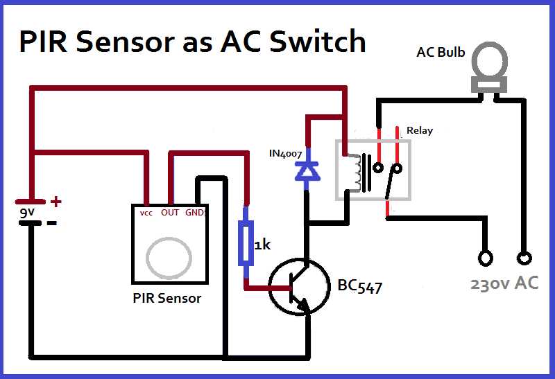
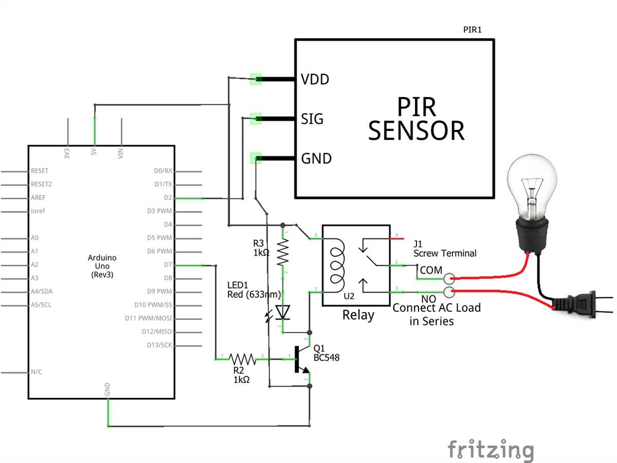
- Identify the different terminals on the PIR sensor. It usually has three terminals: VCC (power supply), GND (ground), and OUT (output).
- Connect the VCC terminal of the PIR sensor to the positive side of the power supply. This provides the necessary voltage for the sensor to function.
- Connect the GND terminal of the PIR sensor to the negative side of the power supply. This completes the circuit and provides the necessary grounding.
- Connect the OUT terminal of the PIR sensor to the input of the device or system that will be triggered by the sensor’s motion detection. This could be a light, alarm, or any other device that needs to be activated when motion is detected.
- If necessary, solder the connections to ensure a secure and reliable connection.
- Double-check all the connections to ensure they are properly made and secure.
- Test the PIR sensor by moving in front of it and checking if the connected device or system responds accordingly.
Following these steps will ensure that the PIR sensor is wired correctly and ready to detect motion in the desired application. It is important to refer to the specific wiring diagram or instructions provided with the PIR sensor, as different models may have slight variations in their wiring configurations.
Common PIR sensor wiring diagrams

PIR sensors, or Passive Infrared sensors, are commonly used in security systems to detect movement. They work by detecting changes in infrared radiation, which is emitted by all objects. PIR sensors are widely used in homes, offices, and other buildings to trigger alarms or turn on lights when motion is detected. Proper wiring is crucial for the accurate functioning of PIR sensors.
There are different wiring diagrams for PIR sensors depending on the type and model of the sensor. Here are some common PIR sensor wiring diagrams:
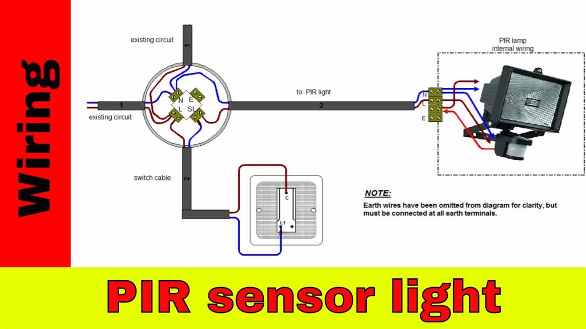
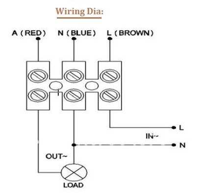
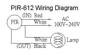
- Single pole, single throw (SPST) diagram: This wiring diagram is used when the PIR sensor is connected to a single load, such as a light. The PIR sensor is connected in series with the load, and the supply voltage is connected to the common terminal of the sensor.
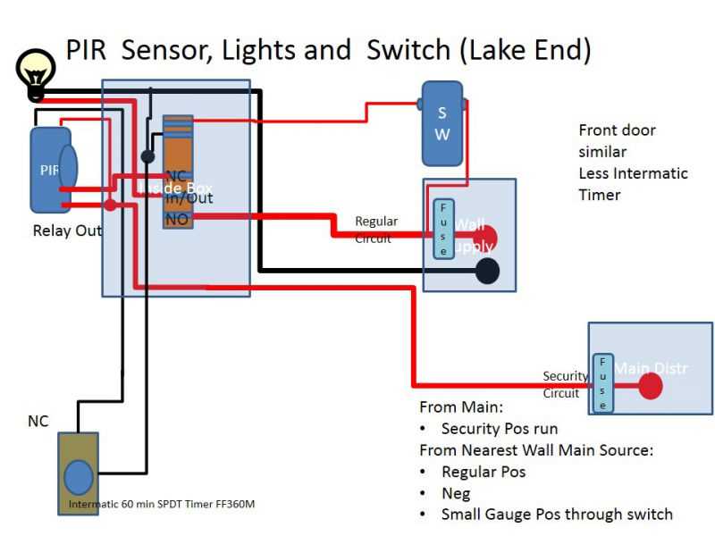
- Double pole, single throw (DPST) diagram: This wiring diagram is used when the PIR sensor is connected to two loads, such as two lights. The PIR sensor is connected in series with the common terminal of the two loads, and the supply voltage is connected to the common terminal of the sensor.
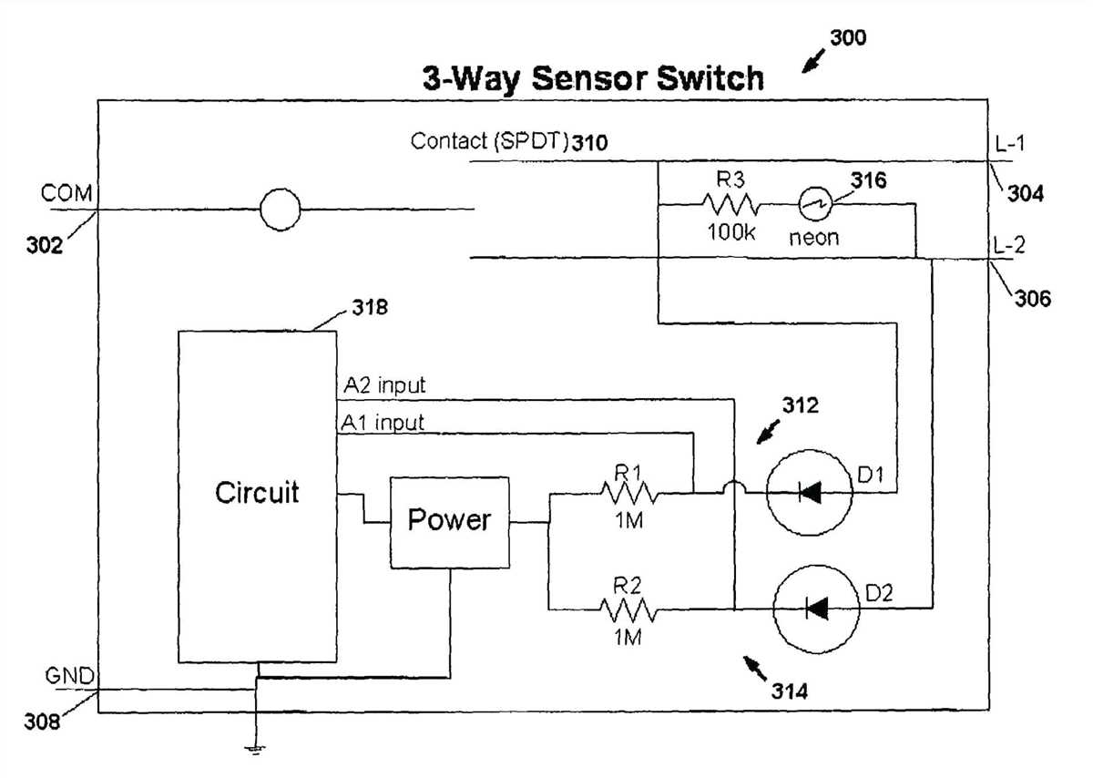
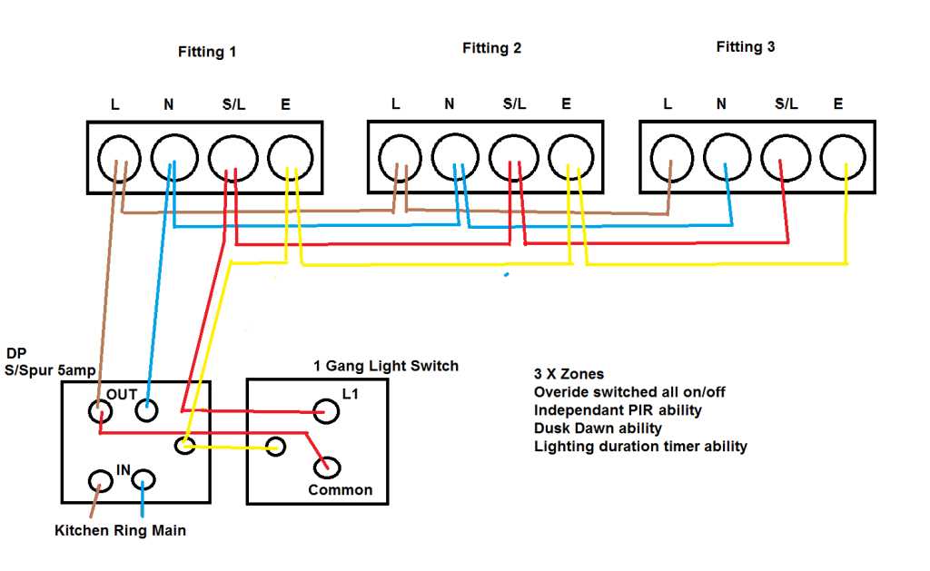
- Three-way diagram: This wiring diagram is used when the PIR sensor is connected to multiple loads, such as two lights controlled by different switches. The PIR sensor is connected in series with the common terminal of the loads, and the supply voltage is connected to the common terminal of the sensor.
It is important to follow the manufacturer’s instructions and guidelines when wiring a PIR sensor. Incorrect wiring can result in false alarms or malfunctioning of the sensor. Additionally, appropriate safety measures should be taken while working with electrical wiring to avoid accidents or damage to the sensor.
Troubleshooting PIR sensor wiring
If you are experiencing issues with your PIR sensor wiring, there are a few common problems that you can check for and troubleshoot. Here are some potential solutions:
1. Verify power supply

Make sure that your PIR sensor is receiving the correct power supply voltage. Check the datasheet or specifications for your specific sensor to determine the correct voltage range. If the power supply voltage is too low or too high, it can cause issues with the sensor’s performance.
2. Check wiring connections
Inspect the wiring connections between the PIR sensor and the rest of your circuit. Ensure that all connections are secure and properly connected. Loose or incorrect wiring can result in unreliable sensor readings or complete failure.
3. Test sensor functionality
To determine if the issue is with the PIR sensor itself, you can perform a functionality test. Use a multimeter to measure the voltage output of the sensor when motion is detected. If the voltage reading fluctuates within the expected range, the sensor is likely working properly. If there is no change in voltage output, the sensor may be faulty.
4. Minimize electrical interference
PIR sensors can be sensitive to electrical interference, which can cause false triggers or erratic behavior. Try to minimize potential sources of interference, such as nearby power lines, motors, or other electronic devices. Additionally, ensure that the sensor is shielded from direct sunlight, as this can also affect its performance.
5. Consider using a pull-up resistor
In some cases, adding a pull-up resistor to the output pin of the PIR sensor can help stabilize its output and prevent false triggers. Consult the datasheet or guidelines for your specific PIR sensor to determine if this is recommended.
By following these troubleshooting steps, you should be able to identify and resolve any wiring issues with your PIR sensor. If the problem persists, consult the manufacturer’s documentation or consider seeking professional assistance.