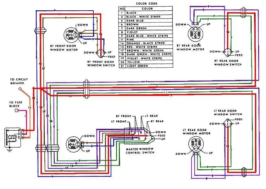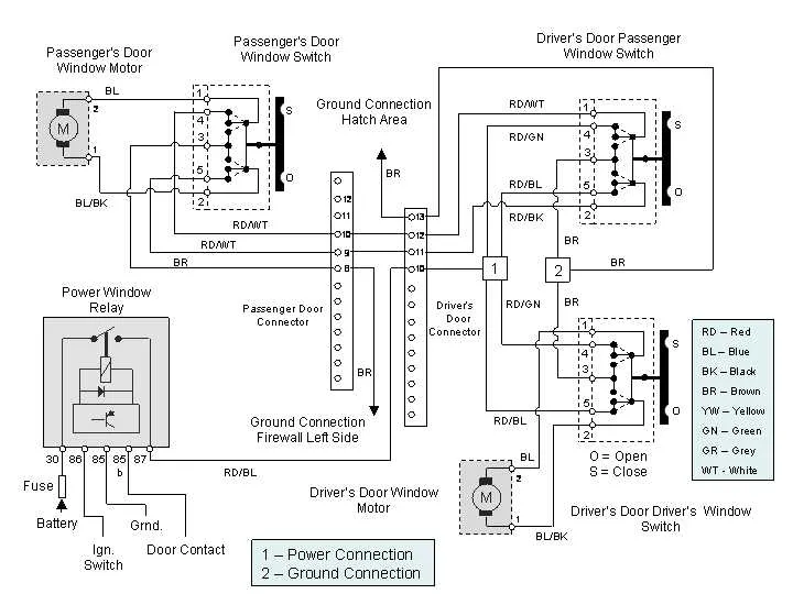
If you need to troubleshoot or rewire the electrical connections for a vehicle’s electric glass system, start by confirming the function of each wire and component. The first step is to identify the power source that feeds the entire setup. This is typically a 12V line, often linked to the car’s battery, which powers the motor responsible for lifting and lowering the glass. Ensure that the switch mechanism operates correctly, as it directs the current to the motor when activated.
Key components: The motor, located near the door, is the central element in this system. Check for continuity between the switch and motor terminals. If the motor fails to engage, it could be an issue with the switch or a short circuit. Use a multimeter to test the continuity of the connections, especially focusing on the relays and fuses that protect the circuit.
Testing tips: Always verify that the ground wire is securely attached to the vehicle’s chassis. A loose or faulty ground can prevent proper operation. Also, ensure that all connections are clean and free of corrosion, which could disrupt the flow of current. Finally, remember to check for any damaged insulation that may cause short circuits and lead to system failure.
Wiring Layout for Electric Glass Elevators
For efficient installation, begin by ensuring the correct wire connections to the motor terminals and the control switch. The switch typically connects to the power supply through a relay, which manages the current flow. Ensure that the motor is grounded properly, as improper grounding can cause system malfunction or electrical hazards.
The most common setup involves a positive and negative connection from the vehicle’s battery to the switch. When the switch is activated, it completes the circuit, sending current to the motor, which lifts or lowers the glass. Each motor must be connected to the switch through dedicated lines to avoid interference between multiple units. For multi-door systems, consider installing a master control switch to synchronize operations across all doors.
Use color-coded cables to identify each line: typically, red for the positive connection, black for the ground, and yellow or blue for the switch signals. The fuse size should match the motor’s rating to protect the system from overloads. Additionally, check the vehicle’s service manual for specific wire configurations and terminal arrangements.
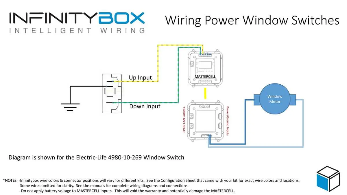
Understanding the Motor Connection Setup

Start by identifying the motor’s terminals: typically, there are four key connections. Two of these are for the motor’s ground and positive supply. The other two are for the switch mechanism that controls the direction of movement.
For the correct wiring, the negative terminal should be connected to a solid ground. The positive terminal must receive the appropriate voltage from the control circuit. To ensure proper directionality, one of the remaining terminals is connected to a switch that toggles between ‘up’ and ‘down’ states, while the last terminal serves as the return for the current when reversing direction.
Check the motor’s voltage rating before connecting, ensuring the system voltage matches the motor’s specifications to prevent damage. Use thick gauge wires for the power supply lines to avoid overheating or voltage drop, especially over long distances.
Proper insulation is critical, especially around the control switch and motor terminals, to prevent short circuits. If testing, use a multimeter to verify continuity and check for any resistance where there shouldn’t be any.
Always verify the motor’s polarity; reversing the connections could cause malfunction. Ensure the polarity is consistent with the vehicle’s design to guarantee smooth operation.
How to Identify and Troubleshoot Common Electrical Issues

Start by checking for a blown fuse in the system’s fuse box. This is the most common issue and can be easily identified by inspecting the fuse related to the component. If the fuse is intact, proceed with further checks.
- Test the switch: Verify that the control switch functions properly. Use a multimeter to test for continuity when pressing the switch. If the switch doesn’t show continuity, it needs to be replaced.
- Check connections: Inspect all connections for signs of corrosion or loose terminals. Tighten any loose connections and clean corroded terminals using contact cleaner.
- Inspect the motor: If the switch and connections are working correctly, but the system still doesn’t respond, test the motor. Apply direct voltage to the motor and observe its operation. If it doesn’t run, the motor may be faulty and requires replacement.
- Examine the circuit for shorts: Using a multimeter, test the circuit for any shorts. A short in the wiring can cause components to malfunction or fail entirely.
- Look for damaged cables: Inspect the cable harness for signs of wear, fraying, or visible damage. Damaged cables should be replaced or repaired with appropriate splicing methods.
Address these issues systematically for an efficient troubleshooting process. If these steps don’t resolve the problem, further diagnosis might be necessary with specialized equipment.
Step-by-Step Guide to Replacing a Power Window Switch
1. Disconnect the battery: Before starting, ensure safety by disconnecting the vehicle’s battery. This will prevent any accidental electrical shorts while working on the system.
2. Remove the door panel: Using a trim removal tool, carefully detach the door panel. Start at the edges and work your way around to avoid damaging the clips. Remove any screws that hold the panel in place.
3. Identify the switch location: Locate the faulty switch. It’s usually attached to the door panel with screws or clips. Examine how it is fixed to understand the best method of removal.
4. Disconnect the switch: Once the switch is exposed, unplug the electrical connector attached to it. Depending on the vehicle, there may be a safety tab that needs to be pressed before the connector can be safely disconnected.
5. Install the new switch: Align the new switch with the mounting area and connect the electrical plug. Ensure that the connection is secure and that the switch is positioned correctly.
6. Test the new switch: Before reassembling the door panel, reconnect the battery and test the new switch to confirm that it operates correctly. Check that all functions are working smoothly.
7. Reassemble the door panel: Once confirmed, reattach the door panel by securing it with screws and snapping the clips back into place. Ensure that everything is securely fastened and aligned properly.
8. Final check: Perform a final test of the switch functionality to ensure everything is working as expected before finishing up the task.