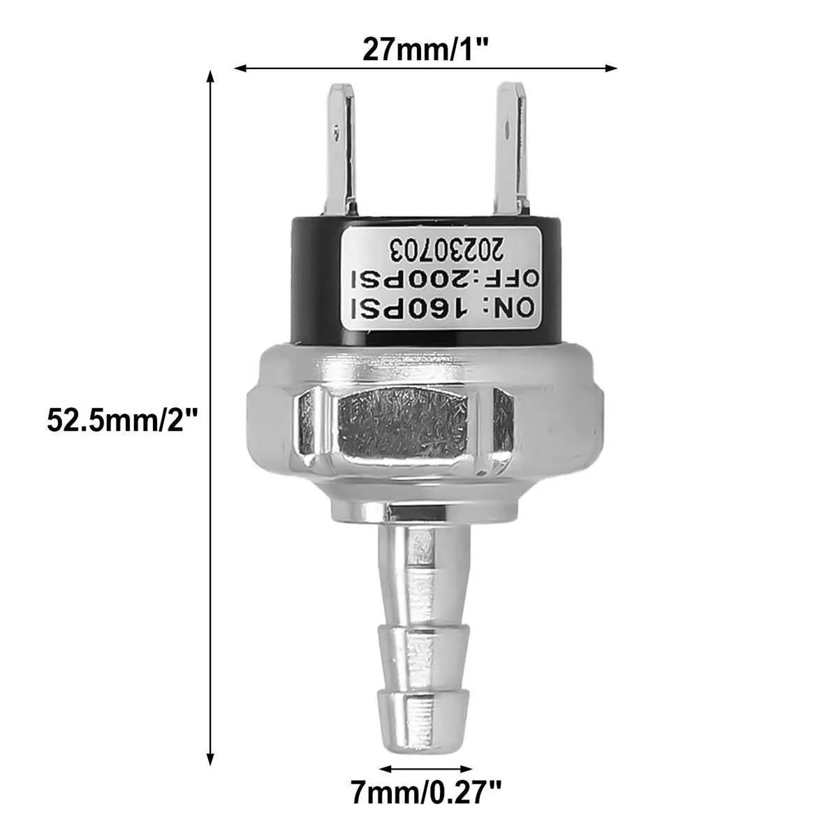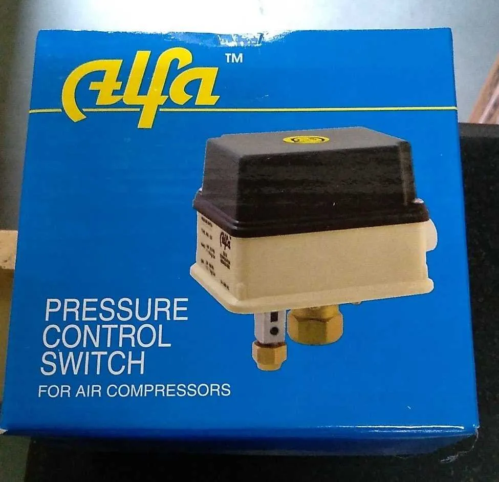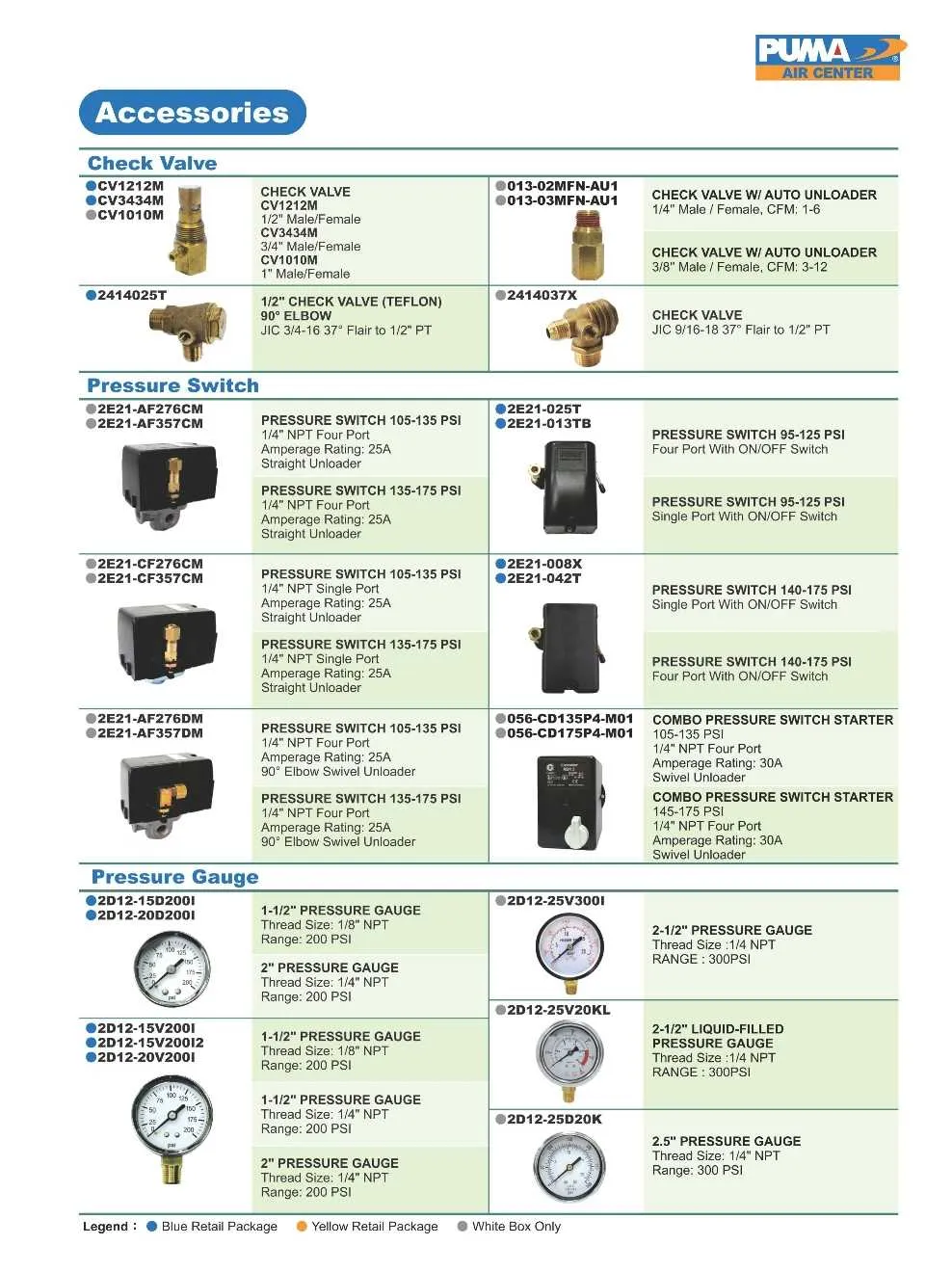
Ensure proper connection of the activation sensor to maintain optimal operation of the pneumatic system. The sensor typically integrates with the motor relay and power supply to regulate pressure levels accurately.
Follow the manufacturer’s specified wiring color codes to prevent miswiring and potential equipment damage. The sensor terminals generally include input, output, and common ground points that must be correctly identified.
Verify that the signal leads align with the relay coil terminals, allowing seamless switching between the motor’s running and resting states. Incorrect hookup may cause frequent cycling or failure to activate safety limits.
Utilize multimeter testing on continuity mode to confirm circuit integrity before finalizing the assembly. This step is critical to avoid malfunctions during operation and to extend the device lifespan.
Control Device Wiring Layout
To ensure proper operation of the device managing tank pressure, follow these wiring guidelines precisely:
- Connect the input terminal to the power supply, typically 120V or 240V AC depending on system specifications.
- Attach the output terminal to the motor starter coil to regulate motor activation.
- Use a grounding wire to prevent electrical hazards and improve system safety.
- Include a capacitor or relay if the motor requires additional starting torque or protection.
Key functional components involved in the control mechanism include:
- A sensing element that detects pressure levels in the tank.
- A mechanical lever or diaphragm that triggers electrical contacts.
- Electrical contacts configured to open or close circuits based on detected pressure changes.
When assembling or troubleshooting, verify the following:
- Correct terminal identification according to manufacturer labels.
- Tight and secure wiring connections to avoid shorts or intermittent faults.
- Calibration settings matching operational pressure thresholds for system activation and deactivation.
Regular inspection of mechanical linkages and electrical contacts ensures reliable switching performance and prolongs service life.
How to Interpret Wiring Connections
Identify the common terminal first, usually marked as “C” or “COM”. This point acts as the main input for electrical flow. Next, locate the normally open (NO) and normally closed (NC) terminals, often labeled accordingly or with numbers such as 1, 2, or 3. NO terminals connect circuits only when activation occurs, while NC terminals allow current flow when the device is inactive.
Verify wire colors against manufacturer codes: black or red commonly serve as line or load connections, while green or bare wires are grounding. Confirm that load wires correspond to motor or pump circuits, ensuring proper relay control. Use a multimeter to check continuity between terminals in different states to avoid miswiring.
Ensure voltage ratings on connection points match system specifications to prevent overload or damage. Double-check that control leads are connected to the actuator mechanism, enabling proper ON/OFF cycling. Always isolate power before modifying any wiring to maintain safety standards.
Troubleshooting Common Wiring Issues in Control Devices

Verify all terminal connections are secure and free of corrosion. Loose or oxidized contacts often cause intermittent operation or failure to activate the mechanism. Use a multimeter to check continuity between terminals and ensure wires are properly crimped or soldered.
Inspect the color coding of cables against the manufacturer’s wiring chart. Mismatched wiring can lead to malfunction or electrical shorts. Confirm the live, neutral, and ground lines follow the correct sequence.
Check for signs of damaged insulation or pinched wires along the cable path. Abrasion or cuts can create shorts or open circuits, resulting in erratic device behavior. Replace any compromised wiring immediately.
Test the coil resistance with an ohmmeter. A reading outside the specified range indicates coil damage, which can prevent proper actuation.
Ensure the control unit is receiving the correct supply voltage. Voltage too low or too high affects switching performance. Use a voltmeter at the input terminals during operation to verify consistency.
Look for accumulation of dust or moisture inside the enclosure. Environmental contaminants may cause electrical bridging or corrosion, disrupting signal transmission. Clean and dry the components as needed.
Replace any burnt or fused fuses in the control circuit. A blown fuse indicates an underlying short or overload condition that must be resolved before restoring power.
Adjusting Cut-in and Cut-out Settings Safely

Always disconnect the power supply before making any adjustments to avoid electrical hazards. Use a calibrated pressure gauge to monitor tank levels precisely during tuning. Locate the adjustment nuts: typically, the lower controls the activation threshold, while the upper sets the shutdown point.
Turn the activation nut clockwise to raise the engagement level by increments of 2-3 psi; counterclockwise lowers it similarly. Adjust the cutoff nut only after setting the starting point, increasing it at least 5 psi above the engagement to ensure proper cycling and avoid rapid motor starts.
Perform changes gradually, testing system response after each small turn. Record original settings before modifications to revert if needed. Avoid exceeding manufacturer-recommended limits–usually between 30 and 150 psi–to prevent equipment damage or unsafe operation.
Once adjustments are complete, restore power and observe multiple cycles to confirm stability and accuracy of the new thresholds. If unusual noise or inconsistent cycling occurs, recheck settings or consult technical documentation for troubleshooting guidance.