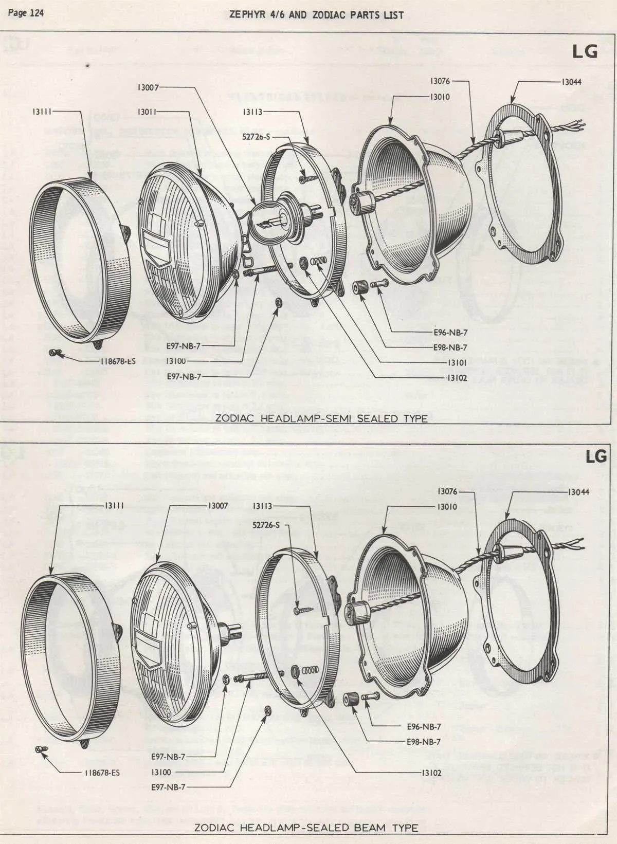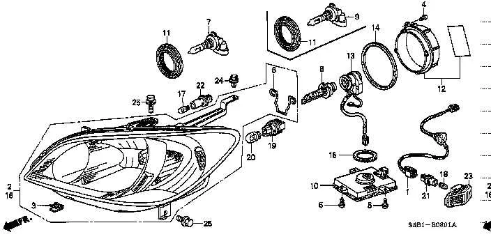
Start with identifying the main enclosure, typically referred to as the lens housing. It protects internal mechanisms from debris and moisture. This casing is usually made from polycarbonate and features UV coating to prevent yellowing over time.
Next, locate the reflector bowl. This metallic surface sits behind the bulb and directs beams forward. In some models, this is replaced or enhanced by projector modules, offering focused illumination through a convex lens.
Observe the light source type: halogen, HID, or LED. Each requires specific socket types and wiring. Halogen uses an H4 or H7 base, HID systems need ballasts, and LEDs often include integrated cooling systems such as fans or heat sinks.
Don’t overlook the adjuster screws. These allow vertical and horizontal alignment to ensure compliance with road regulations and optimal visibility. They’re generally located at the rear of the unit and may require a Torx or Phillips screwdriver.
Finally, inspect the mounting brackets and seals. Rubber gaskets prevent condensation buildup, while metal or plastic mounts secure the unit to the vehicle frame. Proper installation ensures beam stability and prevents misalignment due to vibration.
Essential Components of a Front Lighting Unit

Start by identifying the lens cover – typically made from polycarbonate, it shields internal elements from debris and moisture. Check for UV coating to prevent yellowing over time.
Next, examine the reflector bowl. Its parabolic shape ensures optimal beam focus by redirecting light from the bulb forward. Any tarnish or distortion reduces efficiency and visibility.
Locate the projector module if present. It includes a shutter mechanism to control high and low beam patterns and often enhances precision in modern vehicles.
Inspect the housing, the structural casing that holds all internal elements. It must be intact to prevent water ingress, which can lead to fogging or electrical failure.
Verify the bulb type – halogen, HID, or LED – and ensure compatibility with the socket and wiring harness. Incorrect installations may cause overheating or flickering.
Look for the adjuster screws. These allow vertical and horizontal beam alignment. Misalignment can blind oncoming traffic or reduce road illumination.
Confirm the presence of ventilation ports. These prevent condensation buildup and maintain thermal balance during operation.
How to Identify Each Component in a Headlight Diagram
Start by locating the housing unit – this is the largest structural element, typically molded from durable polycarbonate. It encloses all internal mechanisms and is often fixed to the vehicle frame with mounting brackets.
- Reflector bowl: Positioned behind the bulb, it has a mirror-like surface that channels illumination forward. Identify it by its parabolic shape and metallic coating.
- Projector lens: If present, this element sits in front of the light source and creates a focused beam. Look for a rounded glass or plastic lens, often framed in a metal holder.
- Light source: Common types include halogen capsules, HID burners, or LED modules. Check for wire connectors or ballasts nearby to determine the technology type.
- Shutter mechanism: Found in projector-style assemblies, this movable plate controls the beam pattern. It’s a thin, metallic piece between the bulb and lens, often connected to a small solenoid.
- Ventilation ports: These are small openings with rubber covers or mesh filters to prevent condensation. They’re usually found on the rear or side of the enclosure.
- Adjustment screws: Identify these by their hex or Phillips heads. They allow vertical and horizontal alignment of the beam and are positioned at the rear of the assembly.
Use a flashlight to inspect internal structures without disassembling. Reference manufacturer manuals for component-specific layout variations.
Common Terminology Used in Automotive Headlight Schematics

Always identify the *reflector* as the component directing light forward using a parabolic or free-form surface. Mislabeling it as a lens leads to wiring or adjustment errors.
Use the term *housing* for the external shell enclosing all illumination elements. It ensures moisture protection and alignment integrity. Do not confuse it with the mounting bracket.
Refer to the *bulb socket* as the interface connecting the filament capsule to the electrical harness. This part dictates compatibility with H1, H7, or HID-type sources.
*Beam adjuster* denotes the mechanical or electronic module used to change vertical and horizontal aim. Its misplacement results in failed inspections or glare issues.
Identify the *shroud* as the internal cosmetic or glare-shielding cover, often mistaken for a functional optical element. Its role is primarily aesthetic and regulatory.
Call the *projector module* the sealed optical system containing a lens and cut-off shield, found in high-end systems. This unit shapes and focuses the beam precisely.
Label the *ballast* correctly in xenon-based configurations–it regulates voltage for arc generation and is typically mounted externally or integrated into the rear cover.
Recognize the *ventilation port* or *breather valve* as essential for pressure equalization, preventing condensation inside the enclosure. Blocking it causes fogging and damage.
Use *lens* strictly for the transparent front cover, which may include optical patterns or be clear polycarbonate. Avoid calling this component a cover or shield.
Visual Differences Between Halogen, LED, and HID Assemblies
Halogen units are easily identified by their simple glass bulbs and reflective metal housings. They emit a yellowish light and often have a visible filament inside the bulb. The enclosure tends to be bulkier due to the heat generated and the need for larger reflectors.
LED setups feature multiple small diodes arranged in clusters or strips, producing a bright white or bluish light. Their compact design allows for sleek, angular casings with precise lens optics. These modules usually have a heat sink or cooling fins integrated at the rear to manage temperature.
HID configurations contain xenon gas bulbs housed inside a larger glass capsule, often paired with ballasts visible as separate units. The emitted light is intense white with a slight bluish tint. The assemblies typically have projector lenses that focus the beam, making the front unit appear more complex and glass-covered compared to halogen systems.